
Tv Line Pulse Extractor

This circuit design effectively integrates a sync-generator chip, specifically the LM1881, which serves as a sync separator, to extract the horizontal sync pulse from an NTSC video signal. The LM1881 outputs a clean sync signal that is essential for subsequent processing. The 74LS161 counter is employed to count the number of sync pulses detected. It is configured to reset upon receiving a high signal from the odd/even line output of the LM1881, which indicates the beginning of a new field.
The counting mechanism is designed to account for the peculiarities of the NTSC composite sync signal, which features multiple transitions within a single line. This design choice ensures that the circuit accurately identifies the critical sync pulse associated with line 10 in field 1. The 74LS138 decoder is utilized to decode the output from the counter. When the counter reaches 11 counts, it triggers a low output on pin 4 of the 74LS138, which corresponds to line 10, providing a clear output signal at pin 12.
In addition to its primary function of sync detection, this circuit can be applied in various scenarios where synchronization between different video signals is necessary. By comparing the timing of sync pulses from different sources, adjustments can be made to mitigate any drift between master clocks, ensuring consistent video performance. The feedback mechanism through Q1 ensures that the counter maintains its state until a reset is warranted, allowing for precise control over the counting process and reliable detection of the target sync pulse. Overall, this circuit serves as a robust solution for line synchronization in NTSC video applications. This circuit uses a sync-generator chip, a counter, and a decoder to detect the horizontal sync pulse that occurs a t the beginning of line 10 in field 1 of an NTSC television picture. You can use this circuit to compare the time delay between sync signals at various locations, and to determine and correct for any drift between the two master clocks. The output of the LM1881 sync separator is the key to detecting line 10; the odd/even line goes high on the leading edge of the first equalizing pulse in the middle of line 4.
Thus, you can use this knowledge to find virtually any other line in the field. This particular circuit locates line 10 of field one. The circuit resets the 74LS161 counter until the odd/even line goes high. Then, 74LS161 counts the positive transitions of the sync signal. After 11 positive transitions, the sync pulse drives pin 4 of the 74LS138 decoder low, and the line-10 sync pulse appears at pin 12 of the decoder. (The circuit counts to 11, as opposed to the 6 you might expect—because the composite sync signal contains more than 1 pulse per line).
The counter remains in its maximum-count state until the sync separator causes a reset because Q1 feeds the inverted terminal-count output back to the parallel-enable input.
Related Circuits
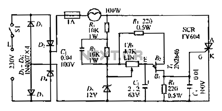
An AC voltage of 30V is rectified. The positive terminal is connected to a fuse and a 100W bulb, while the negative terminal is connected to a thyristor. A Zener diode provides a stable bias voltage. A variable resistor...

The voltage Vc1 increases linearly when the pull-up resistor RA in the monostable circuit is replaced with a constant current source, resulting in the generation of a linear ramp. The figure illustrates the linear ramp generating circuit and the...
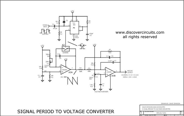
This circuit is designed to convert a square wave input signal into a voltage output. The voltage produced is proportional to the time interval between the edges (period) of the signal, rather than its frequency. The operational range of...
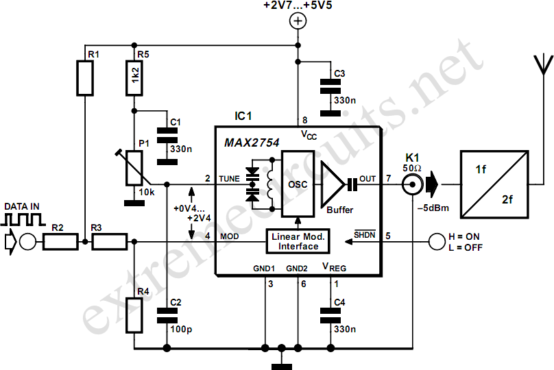
High-frequency voltage-controlled oscillators (VCOs) are challenging to construct. Maxim has developed an integrated 1.2 GHz oscillator, the MAX2754. The center frequency is adjustable via the TUNE input, while a linear modulation input enables frequency modulation. This integrated circuit (IC)...
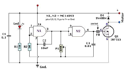
A quad 2-input NAND Schmitt trigger circuit can be designed using the MC14093 CMOS type IC, which serves as a simple pulse width modulation (PWM) controller electronic project. This PWM controller is straightforward and requires only a few external...
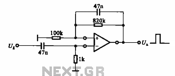
It demonstrates the use of various types of pulse signal generating circuits utilizing operational amplifiers. The circuit described involves the implementation of pulse signal generators using operational amplifiers (op-amps), which are versatile components frequently employed in analog electronics. These circuits...