
Linear amplifier

The 10W HF linear amplifier circuit is designed to amplify high-frequency signals with a power output of 10 watts. This circuit is particularly useful for amateur radio applications, audio amplification, and various RF transmission tasks. The schematic typically includes a series of components such as transistors, resistors, capacitors, and inductors, which work together to achieve the desired amplification.
The core of the amplifier usually consists of one or more bipolar junction transistors (BJTs) or field-effect transistors (FETs) configured in a common-emitter or common-source arrangement. This configuration is chosen for its ability to provide significant voltage gain while maintaining a relatively simple design.
Input and output stages are critical in ensuring that the amplifier operates efficiently. The input stage often includes a matching network to optimize the impedance seen by the source, minimizing signal loss. Capacitors may be used for AC coupling, allowing only the desired frequency range to pass through while blocking DC components.
The output stage is designed to deliver the amplified signal to the load, which could be an antenna or other RF circuitry. It is essential to include appropriate filtering components, such as low-pass filters, to suppress unwanted harmonics and ensure that the output signal remains clean and within the desired frequency range.
Power supply considerations are also vital in the design of this amplifier. A stable DC power supply is required to ensure consistent performance. Additionally, bypass capacitors are often placed near the power supply pins of the active devices to filter out any high-frequency noise that could affect the amplifier's operation.
Thermal management is another crucial aspect of the design. Heat sinks may be required for the transistors to prevent overheating during operation, especially when driving higher power levels. Proper layout techniques should be employed to minimize parasitic inductances and capacitances, which can adversely affect performance at high frequencies.
This circuit can be constructed on a printed circuit board (PCB) or a breadboard for prototyping purposes. Following the schematic closely and ensuring that all components are placed correctly will lead to a successful build of the 10W HF linear amplifier.10W HF linear amplifier circuit schematics free electronic circuits diagram wiring design plans schema DIY projects handbook guide tutorial schematico electrG³nico schG©matique diagrama esquemG tico projeto elektronisch schematisch schaltplan schematy circuito shema … µ ° skematisk Schaltbild schematisk schaltung application manual 🔗 External reference
Related Circuits
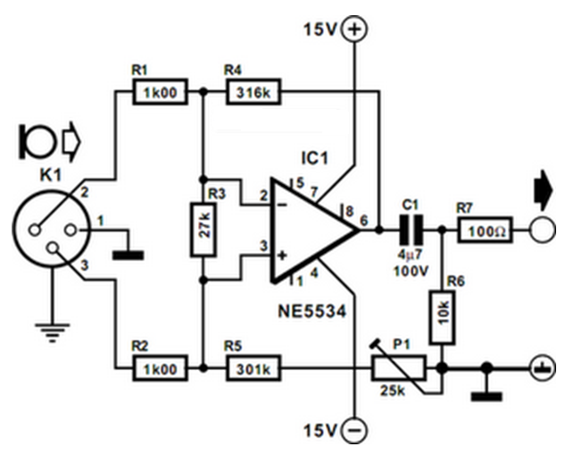
The preamplifier is designed for use with dynamic (moving coil MC) microphones with an impedance of up to 200 ohms and balanced terminals. It features a straightforward design and can be regarded as a single-stage instrument amplifier utilizing a...
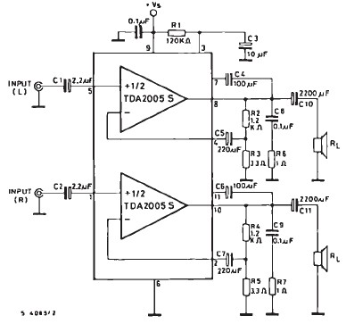
The TDA2005 car audio amplifier circuit is specifically designed for use in devices such as car radios and CD players. This amplifier circuit utilizes the TDA2005 audio integrated circuit (IC), which can deliver a maximum output power of 20...
This design is based on an 18 Watt audio amplifier and was developed primarily to meet the needs of users who are unable to find the TLE2141C chip. It utilizes the widely available NE5532 dual integrated circuit; however, its...
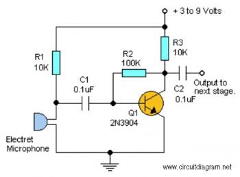
This straightforward circuit offers substantial amplification for weak audio signals, such as those from an electret microphone. It can be utilized in conjunction with an RF oscillator to create a highly sensitive RF transmitter. The audio microphone preamplifier circuit...
This schematic diagram illustrates a 70W power amplifier utilizing MOSFET technology for audio systems. Alternative input stage transistors include the Toshiba 2SA970BL and 2SC2240BL, which serve as suitable substitutes for the Hitachi 2SA1085E. The 70W power amplifier is designed to...
That Circuit is a UHF TV linear amplifier for small TV transmitters with output around 100-200mW. The transistor BGQ136 comes with SOT-122 case has gain of 13dB at 800MHz. So with input 100mW you get 2W output and for...