
Liquid-Crystal Display (LCD) Tester
The operation of liquid-crystal displays relies on the precise interaction between the applied voltage and the liquid crystal material. This material is sensitive to electric fields, allowing for the manipulation of light passing through the display. The tester's square-wave generator is essential for maintaining the integrity of the display during testing. By ensuring that the voltage applied is purely alternating, the risk of damaging the display is minimized. The choice of the 4047 IC is strategic, as it not only enables the generation of a symmetrical waveform but also provides flexibility in frequency selection, which can be adjusted based on the specific requirements of the LCD being tested.
The design of the tester should include a user-friendly interface, possibly with indicator LEDs to signal when a segment is activated. Additionally, incorporating a variable resistor in the circuit allows for fine-tuning of the voltage applied, facilitating the exploration of the display's operational range. Proper grounding and shielding techniques should be employed to prevent interference and ensure accurate readings. The layout of the circuit should be compact yet robust, with attention to the placement of components to minimize noise and enhance performance. Overall, the tester serves as an invaluable tool for diagnosing and troubleshooting liquid-crystal displays, providing insights into their functionality without risking damage to the components.Liquid-crystal displays come in all sorts and sizes, and this applies also to their pinouts. In fact, many of these displays cannot be used properly without the manufacturers` documentation. But, of course, this can never be found when it is needed, and a small tester to unravel the terminals may, therefore, be found very handy. A liquid-crystal d isplay consists of two thin sheets of glass, the facing surfaces of which have been given thin conducting tracks. When the glass is looked through at right or near-right angles, these tracks cannot be seen. At certain viewing angles, they become visible, however. The space between the sheets of glass is filled with a liquid that, stimulated by an electric voltage, alters the polarization of the incident light.
In this way, segments may appear light or dark and give rise to the display of lines or shapes. A segment may be tested by applying an alternating voltage of a few volts across it. Note that the application of a direct voltage will damage the display irreversibly: the resulting current will remove the tracks. The alternating voltage should contain not even a tiny direct voltage component. An alternating current also removes part of the tracks when the current flows in one direction, but restores it when the current flows in the opposite direction.
The tester described here consists of a square-wave generator that produces an absolutely symmetrical alternating voltage without any d. c. component. Most logic oscillators are incapable of producing a squarewave signal: they generate rectangular waveforms whose duty cycle hovers around the 50%.
The 4047 used in the tester has a binary scaler at its output that guarantees symmetry. The oscillator frequency is about 1 kHz. It may be powered from a 3 9 V source. Normally, this will be a battery, but a variable power supply has advantages. It shows at which voltage the display works satisfactorily and also that there is a clear relationship between the level of the voltage and the angle at which the display is clearly legible. The tester draws a current not exceeding 1 mA. The test voltage must at all times be connected between the common terminal, that is, the back plane, and one of the segments.
If it is not known which of the terminals is the back plane, connect one probe of the tester to a segment and the other successively to all the other terminals until the segment becomes visible. Note, however, that there are LCDs with more than one back plane. Therefore, if a segment does not become visible, investigate whether the display has a second back plane terminal.
🔗 External reference
Related Circuits
The RF Tester (A3014) is a combination of four circuits designed to test various circuit concepts by implementing them and providing enhanced support circuits for their development. The Modulating Transmitter (A3014MT) replaces the previous Modulating Transmitter (A3001A) and allows...
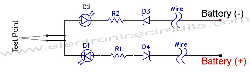
12V Vehicle Electrical Wiring Tester Circuit. This tester is useful for checking vehicle electrical circuits. Two LEDs indicate whether the circuit is live or not. The 12V vehicle electrical wiring tester circuit is designed to provide a simple yet effective...
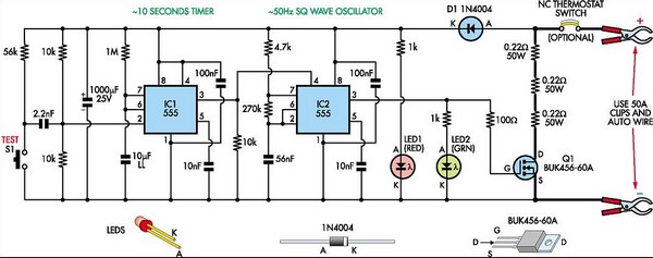
This circuit is designed to assess the condition of lead-acid and gel cell batteries with capacities exceeding 20Ah. It switches a load of approximately 18A at a frequency close to 50Hz, allowing for the measurement of the battery's internal...
This is the seventh part of an ongoing series about building a low-cost, open-source streaming internet radio. If you have not already, check out the previous parts for some background about the project. In part six, UNIX-style shell commands...
Sometimes when experimenting with different soundcards and MIDI interfaces it is useful to see if there is some data going in MIDI interface. This can be easily tested with this adapter, which converts the midi signals to visible light...
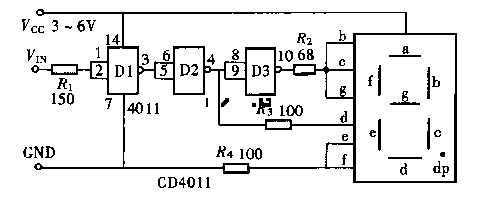
The door circuit logic pen text display can take many forms, utilizing various logic gates such as inverters, NAND gates, NOR gates, and others. A logical pen, exemplified by the NAND gate CD4011, can be used in conjunction with...