RF Tester
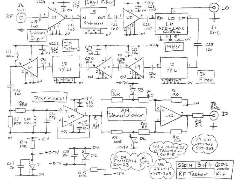
The RF Tester (A3014) is a combination of four circuits designed to test various circuit concepts by implementing them and providing enhanced support circuits for their development. The Modulating Transmitter (A3014MT) replaces the previous Modulating Transmitter (A3001A) and allows the user to adjust the DC voltage applied to a MAX 2624 using a potentiometer, with the modulation waveform AC-coupled through a BNC socket. The SAW Oscillator (A3014SO) employs precise SAW filters to generate accurate RF reference frequencies, serving as stable local oscillators for downshifting RF signals or as reference RF signals for calibrating receivers. The TQFP-48 Programmer (A3014TP) utilizes a TQFP-48 socket to program Lattice Semiconductor LC4064 chips in 48-pin thin quad flat pack packages, enabling programming before mounting on a transmitter, thus eliminating the need for programming connections on the transmitter. The Demodulating Receiver (A3014DR) accepts LO and RF signals through BNC sockets, with an optimal LO level of +7 dBm and an RF signal in the 900-MHz ISM band. The output of the A3014DR is the demodulated RF signal, akin to that of the A3005B. This circuit leverages the phase shift and attenuation of SAW filters to form a SAW oscillator, offering a selection of three different SAW filter footprints. The choice of footprint is made using resistors R1-R3 and capacitors C4-C6, corresponding to 3.0-mm, 3.8-mm, and 5.0-mm surface mount packages. It is noted that the 5.0-mm footprint on the A3014SO is incorrectly configured, using pins 2 and 6 for input and output instead of pins 1 and 5. The SAW filters in position L3 may function inconsistently. The circuit employs capacitive coupling to select L3, a B3570 from Epcos, which oscillates at 868.4 ±1 MHz, with a power output of +13 dBm at J2. Initial testing with capacitors C2 and C3 of 1 F led to failures of U2 and U3 upon power connection; increasing these capacitors to 10 F resulted in successful operation over one hundred power connections. The coupling mechanism connecting the SAW filter to its oscillation amplifier (U2 in the schematic) influences the oscillator's frequency and stability. Handling the circuit can disrupt oscillations in the SAW filter pass-band, leading to parasitic oscillations outside this range. Potential causes include the UPS2764's stability being limited to near-50 Ω loads and the SAW filters not behaving as 50 Ω loads outside their pass-band. To mitigate such transmission, careful board layout with coplanar waveguides, as seen in the A3021B, is recommended. These oscillations outside the SAW filter pass-band are referred to as parasitic oscillations. A table illustrates the effects of various components for R2 and C5 when connecting an AFS869S3 in a 3.8-mm package from Abracon, whose pass-band is 869 ±4 MHz. The stability of the AFS869S3 is noted to be better with inductive coupling, while other SAW filters exhibit varying stability characteristics with different coupling types. In all instances, the oscillator may power up into parasitic oscillation.
The RF Tester (A3014) integrates multiple functionalities, enabling comprehensive testing and development of RF circuits. Each component serves a distinct role, ensuring versatility and adaptability in circuit design. The Modulating Transmitter (A3014MT) facilitates modulation control, while the SAW Oscillator (A3014SO) provides precise frequency references essential for accurate signal processing. The TQFP-48 Programmer (A3014TP) streamlines the programming process of Lattice Semiconductor chips, enhancing operational efficiency by allowing pre-programming before assembly. The Demodulating Receiver (A3014DR) is crucial for receiving and processing RF signals, ensuring optimal performance within the specified frequency range.
The design considerations for the SAW Oscillator highlight the importance of component selection and layout in maintaining circuit stability. The use of various SAW filter footprints allows for flexibility in design, catering to different application requirements. Careful attention to coupling methods and component specifications is critical to prevent parasitic oscillations, which can adversely affect circuit performance. The documented findings regarding component interactions provide valuable insights for engineers working with similar RF circuit configurations, emphasizing the need for thorough testing and validation during the design process.The RF Tester (A3014) is a combination of four circuits. Its purpose is to test several circuit ideas, both by implementing them, and by providing better support circuits for their development. The Modulating Transmitter (A3014MT) replaces our original Modulating Transmitter ( A3001A ). The A3014MT allows you to set the DC voltage applied to a MAX 2624 with a potentiometer, and then AC couple your modulation waveform through a BNC socket. The SAW Oscillator (A3014SO) uses precise SAW filters to produce precise RF reference frequencies. We can use these as stable, accurate local oscillators for downshifting our RF signals, or we can use them as reference RF signals with which to calibrate our receivers. The TQFP-48 Programmer (A3014TP) uses a TQFP-48 socket to program Lattice Semiconductor LC4064 chips in 48-pin thin quad flat pack packages.
This allows us to program the chips before mounting them on a transmitter, so that no programming connection need be present on the transmitter. The Demodulating Receiver (A3014DR) takes as input an LO and RF signal through BNC sockets. The LO should be +7 dBm for optimal operation of the A3014DR`s mixer. The RF signal should be in the 900-MHz ISM band. The A3014DR output is the demodulated RF signal, similar to that of the A3005B. This circuit uses the phase shift and attenuation of SAW filters to create a SAW oscillator. The circuit gives us a choice of three different SAW filter footprints to choose from. We select which footprint to use by means of R1-R3 and C4-C6. The footprints L1, L2, and L3 are for 3. 0-mm, 3. 8-mm, and 5. 0-mm surface mount packages respectively. The 5. 0-mm footprint on the A3014SO is incorrect. It uses pins 2 and 6 for the input and output respectively, instead of pins 1 and 5. The SAW filters in position L3 sometimes work but not always. Figure: SAW Oscillator (A3014SO). Note the three available SAW filters, L1, L2, and L3. As show, the circuit uses capacitive coupling to select L3, a B3570 from Epcos, which oscillates at 868.
4 ±1 MHz. The power output on J2 is is +13 dBm. With C2 and C3 both 1 F, we found that U2 and U3 would blow occasionally when we plugged power into the circuit. We increased C2 and C3 to 10 F. After that, U2 and U3 survived one hundred power connections on both the SAW Oscillators we used in our experiments.
The coupling we use to connect the SAW filter to its oscillation amplifier (U2 in the schematic ) affects the frequency and stability of the oscillator. No matter what coupling we use, it is always possible, by touching and handling the circuit, to stop oscillations in the SAW filter pass-band, and provoke a parasitic oscillation outside the SAW filter pass-band.
These oscillations may have one of two causes. The UPS2764 is stable only for near-50 © loads, and the SAW filters do not act like 50- © loads outside their pass band. The amplifier may be transmitting its output to its input by means of the long tracks on the circuit board.
If we want to suppress such transmission, we must lay out the board more carefully, with coplanar wave guides, as in the A3021B. In any case, we call these oscillations, outside the SAW filter pass-band, parasitic oscillations. The following table shows the effect of various components for R2 and C5 when we used them to connect an AFS869S3 in a 3.
8-mm package from Abracon. The filter`s pass-band is 869 ±4 MHz. In each case, we describe how easy it is to provoke parasitic oscillations. Table: Effect of Coupling Components on Stability. R2 and C5 are the P0805 surface-mount parts defined in the A3014SO schematic. They connect L2 to the oscillation amplifier. In this case, L2 is the AFS869S3. The AFS869S3 is stable with inductive coupling. The same is not true for other SAW filters. Some are more stable with inductive coupling than with capacitive, others are less stable. In all cases, the oscillator sometimes powers up into parasitic oscillation 🔗 External reference

