
Solar Charger for 6V 4.5Ah Battery
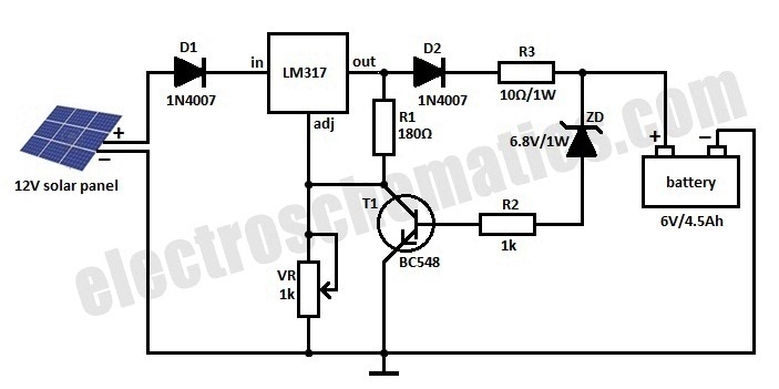
The solar charger circuit operates effectively by utilizing solar panels to convert sunlight into electrical energy. The solar panel generates a nominal output of 12 volts DC, which is suitable for charging a 6-volt battery. The LM317 voltage regulator is crucial in maintaining a steady output voltage during the charging process. The output voltage can be adjusted using the variable resistor (VR) to ensure that the battery receives the appropriate voltage level for optimal charging, typically set at 9 volts in this design.
Diode D1 serves to protect the circuit by allowing current to flow in one direction—into the battery—while preventing reverse current flow that could damage the solar panel. Resistor R3 is strategically placed to limit the charging current, thus preventing overcharging and extending the lifespan of the battery. Diode D2 also plays a critical role in maintaining battery health by preventing discharge when the solar panel is not generating power.
The inclusion of transistor T1 and Zener diode ZD adds an essential safety feature to the circuit. This combination acts as an automatic cutoff switch that disconnects the charging current once the battery reaches a predetermined voltage level of 6.8 volts. This feature is vital for preventing overcharging, which can cause damage to the battery and reduce its overall efficiency and lifespan. When the battery voltage exceeds this threshold, the Zener diode conducts, providing sufficient base current to turn on transistor T1. This action grounds the output of the LM317, effectively stopping the charging process until the battery voltage drops below the cutoff level.
Overall, this solar charger circuit is a well-designed solution for renewable energy applications, providing efficient battery charging while incorporating necessary safety features to protect both the battery and the charging circuit.Here is a solar charger circuit that is used to charge Lead Acid or Ni-Cd batteries using the solar energy power. The circuit harvests solar energy to charge a 6 volt 4. 5 Ah rechargeable battery for various applications. The charger has Voltage and Current regulation and Over voltage cut off facilities. 12 volt DC is available from the panel to ch arge the battery. Charging current passes through D1 to the voltage regulator IC LM 317. By adjusting its Adjust pin, output voltage and current can be regulated. VR is placed between the adjust pin and ground to provide an output voltage of 9 volts to the battery. Resistor R3 Restrict the charging current and diode D2 prevents discharge of current from the battery.
Transistor T1 and Zener diode ZD act as a cut off switch when the battery is full. Normally T1 is off and battery gets charging current. When the terminal voltage of the battery rises above 6. 8 volts, Zener conducts and provides base current to T1. It then turns on grounding the output of LM317 to stop charging. 🔗 External reference
Related Circuits
With the rapid development of the social economy, the demand for electric energy continues to increase. In light of the diminishing availability of non-renewable energy sources, such as fossil fuels, many countries are recognizing the importance of energy conservation...
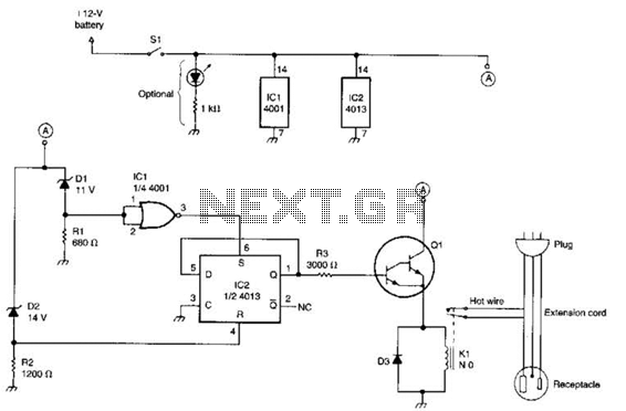
This circuit utilizes a pair of Zener diodes to monitor the voltage of a 12-V battery. When the voltage drops below 11 V, diode D1 ceases to conduct, causing pin 3 of flip-flop IC2 to go high. This action...
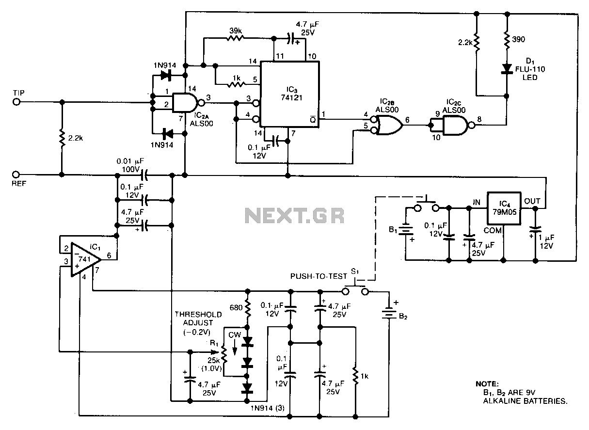
Oscilloscope measurements of ground noise can be unreliable because noise can enter your circuit via the scope's three-pronged power plug. This issue can be mitigated by utilizing the ground-noise tester described. The circuit operates on two 9-V batteries and...

This is a simple and low-cost NiCd and NiMH battery charger. The schematic diagram indicates that the charging current (I) should be set to 1/10 of the battery's rated capacity. For instance, if the battery has a rated capacity...
This is a DIY electronics project designed to enhance circuit design and building techniques. Copper lanterns were purchased and fitted with a circuit similar to outdoor solar lights. The circuit design is adapted from a simple design found on...

A printed circuit board (PCB) was presented along with a schematic detailing the arrangement of components required for the activation of an LED on the board. The purpose of the PCB is to facilitate planning for the eventual construction...