
SWR warning indicator
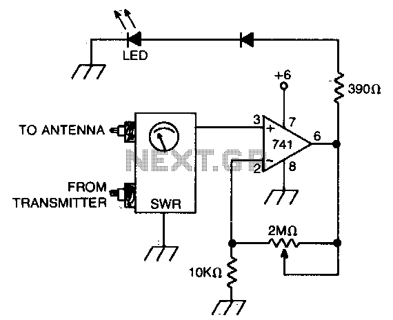
The circuit involves an operational amplifier configured in a feedback loop to process the DC voltage signal derived from the SWR meter. The SWR meter measures the ratio of the power reflected from the load to the power delivered to the load, providing an indication of the efficiency of the antenna system. The output voltage from the SWR meter is fed into the non-inverting input of the op amp.
To enable adjustment of the SWR reading, a potentiometer is included in the circuit. This potentiometer allows for fine-tuning of the reference voltage applied to the inverting input of the op amp. As the potentiometer is adjusted, the threshold at which the op amp will activate the LED changes, indicating a specific SWR level.
The op amp is configured in a comparator mode, where it compares the voltage from the SWR meter against the adjustable reference voltage. When the voltage from the SWR meter exceeds the set threshold, the output of the op amp goes high, turning on the LED. This visual indication serves as an alert to the user that the SWR has reached a predetermined level, necessitating attention to the antenna system.
Power supply considerations for the op amp must also be addressed, ensuring that it operates within its specified voltage range. Proper decoupling capacitors should be placed close to the op amp’s power pins to mitigate any noise that could affect performance. Additionally, the selection of the op amp should consider bandwidth and slew rate to accommodate the frequency response of the SWR meter.
Overall, this circuit design provides a straightforward method for monitoring SWR levels, enhancing the usability of the antenna system by providing a clear visual indication when the SWR exceeds acceptable limits.Op amp with dc input from SWR meter can be adjusted to preset the SWR reading at which the LED lights. 🔗 External reference
Related Circuits
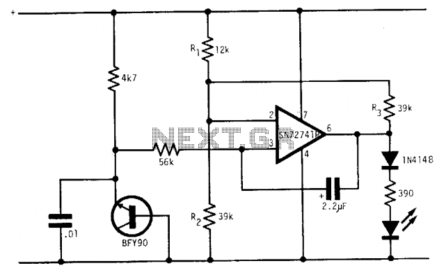
Under optimal battery conditions, the LED remains off. As the battery voltage decreases, the LED starts to flash, and when the battery reaches a low voltage condition, the LED illuminates continuously. This circuit is designed for use with a...
A peak level indicator is a device that signals when a signal surpasses a specific maximum value. It proves to be particularly beneficial in applications such as tape recorders and mixing consoles. A crucial requirement for a peak level...
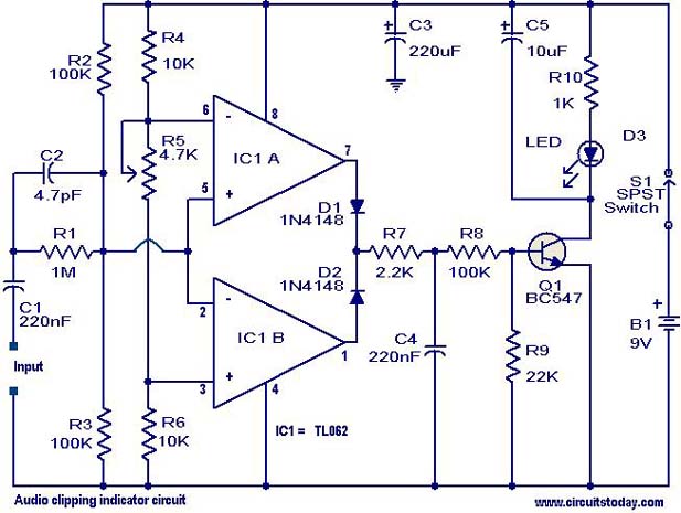
This circuit is designed to detect clipping in a specific waveform. Clipping occurs when the amplitude of a waveform decreases before reaching its expected limit. The circuit activates an LED as an indication that the tested signal is experiencing...
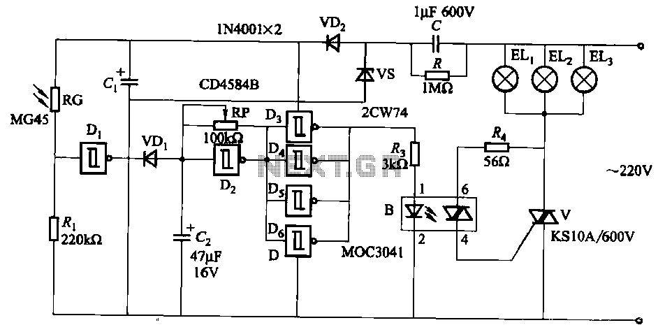
The circuit utilizes a CD4584B six Schmitt trigger integrated circuit (IC) with components Di and Ri forming a photometric circuit. D2, along with RP and C2, comprises an adjustable frequency ultra-low frequency oscillation device, where RP serves as an...
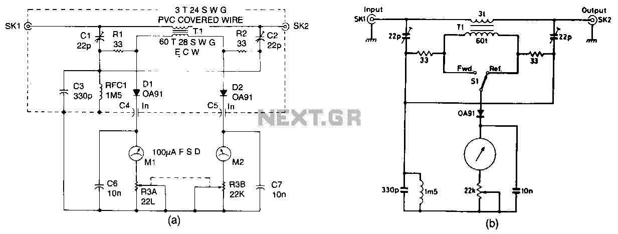
The design presented is a straightforward unit intended for QRP (low-power) operation across all authorized frequencies up to 30 MHz. It utilizes a toroidal transformer (T1). The secondary winding of T1 captures a small portion of RF power, both...
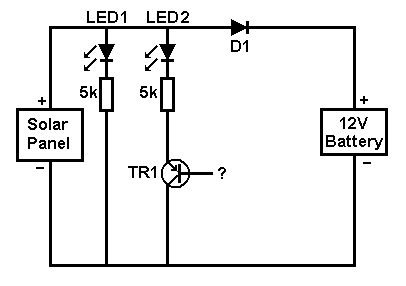
A small solar panel is used to maintain a 12V car battery. The panel provides approximately 75mA of current to the battery under full sunlight conditions. The described circuit employs a solar panel specifically designed for battery maintenance applications. The...