
Light sensor switch circuit

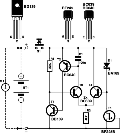
This light sensor switch circuit is designed for efficient operation in environments where automatic lighting control is desired. The circuit leverages a phototransistor (T3) to detect ambient light levels. When light is present, T3 conducts, which in turn keeps T5 off, preventing the lamp from being activated. The base-emitter junction of transistor T2 is strategically placed in parallel with T3, ensuring that T2 remains off during daylight conditions. As darkness sets in, resistor R7 provides the necessary base current to T2, allowing it to turn on.
Once T2 is activated, it initiates the counting process within the integrated circuit IC1, which is likely a timer or counter IC. The internal oscillator of IC1 generates clock pulses that are counted, and during this time, the lamp remains illuminated. The duration for which the lamp stays on is determined by the timing configuration of the circuit, which may involve additional components not explicitly detailed in the description, such as resistors and capacitors connected to the IC.
After the predetermined time has elapsed, the output of Q13 transitions to a high state, which subsequently turns off T4. This action deactivates the relay, causing the relay's LED to extinguish and the lamp to turn off, effectively completing the cycle. The entire circuit is designed to operate directly from the 220V AC mains supply, making it convenient for residential or commercial lighting applications. The diodes (D1 to D5) play a crucial role in converting the AC voltage to a usable DC voltage for the circuit, while capacitor C4 smooths out any voltage fluctuations, ensuring stable operation of the circuit components. This design emphasizes energy efficiency and automation, making it suitable for various lighting control scenarios.This light sensor switch circuit allows the automatic connection of a lamp when the light is low (at nightfall) and will maintain the lamp ON for a certain period of time. From the moment that T4 and T5 are opened, relay`s LED start to light and powers the lamp. As soon as one of the transistors is blocked the lamp will go OFF. The phototransistor T3 will be the one that blocks T5 if there is light that falls on T3. The T2 ²s base-emitter junction is connected in parallel with T3 and so will be blocked as long there is light. T2 will continuously resest IC1 whose counter outputs will be in 0 ³ state. When the night falls R7 provides base current for T2 and the transistor starts to conduct. The counter can now starts to count the impulses from the internal oscillator and in this time the light will bulb will stay lit.
After a time, when the output of Q13 goes in state 1 ³ T4 is blocked. This causes the relay`s LED to go off and the lamp too. There is no need for external power supply because the light sensor switch is powered directly from the 220V mains. D1 D5 diodes rectifies the voltage and C4 filters it. 🔗 External reference
Related Circuits
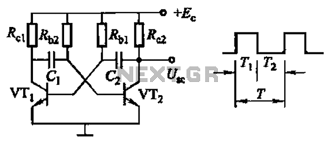
Common non-sinusoidal oscillator circuit, waveform and frequency formula - square wave oscillator - self-excited multivibrator The common non-sinusoidal oscillator circuit, specifically the square wave oscillator, is a fundamental electronic circuit utilized to generate square wave signals. It operates based on...
This circuit can be used to operate an electric strike or an electromagnetic lock on a door. It is not the door being opened/closed, but a small electromagnetic strike which unlocks the door. The opener has the following features...
The FM demodulator circuit, as illustrated in the figure, utilizes a 4046 Phase-Locked Loop (PLL) integrated circuit to convert the intermediate frequency FM input signal into a lower frequency output. The FM demodulator circuit based on the 4046 PLL IC...
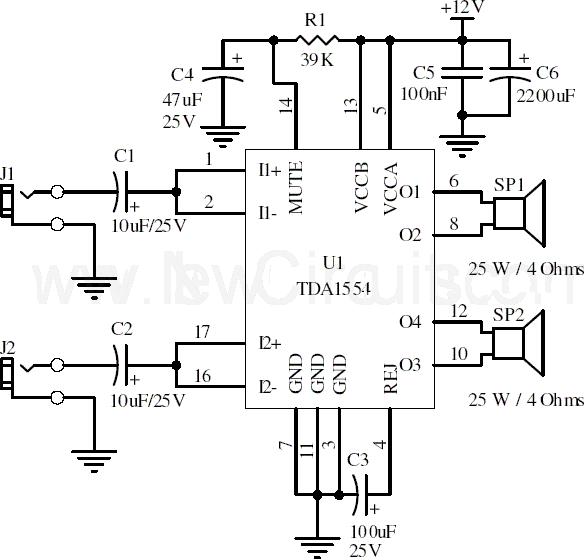
This document presents a 22-watt stereo audio power amplifier circuit diagram utilizing the TDA1554 integrated circuit from NXP Semiconductors (formerly known as PHILIPS Semiconductors). The circuit is designed to amplify stereo signals effectively. It dissipates approximately 28 watts of...

The following circuit illustrates photovoltaic light sensors in a solar tracker. Features include accuracy, low cost, simplicity, and a single-axis electronic design. The photovoltaic light sensor circuit is designed to optimize the alignment of solar panels with respect to the...
Is the battery empty, or is there something wrong with the device? This question can be challenging when a battery-powered device, such as a Walkman, appears to be non-functional upon switching it on. Before seeking professional servicing, the initial...
Warning: include(partials/cookie-banner.php): Failed to open stream: Permission denied in /var/www/html/nextgr/view-circuit.php on line 713
Warning: include(): Failed opening 'partials/cookie-banner.php' for inclusion (include_path='.:/usr/share/php') in /var/www/html/nextgr/view-circuit.php on line 713