LM139 Measure delay generator Schematic Diagram
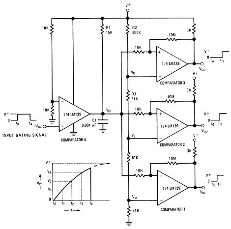
A measure delay generator, also identified similarly to a sequence generator, is a device that provides output signals at specified time intervals from a time reference. It automatically resets when the input signal returns to ground. The schematic illustrates the design of a measure delay generator circuit diagram using the LM139. The LM139 is a precision comparator that enables sensing close to ground, eliminating the need for dual power supplies and minimizing power consumption, making it suitable for battery-operated setups.
The measure delay generator circuit utilizing the LM139 comparator is designed to provide precise timing control for various applications. The circuit operates by comparing an input voltage to a reference voltage, which is set using a resistor divider network. When the input signal exceeds the reference voltage, the LM139 outputs a high signal, initiating a timing interval. The duration of this interval is determined by external timing components, typically a resistor-capacitor (RC) network, which sets the charge and discharge time constants.
Upon reaching the specified delay, the output signal transitions to a low state. The circuit is designed to reset automatically when the input signal returns to ground, ensuring that the timing cycle can repeat without manual intervention. This feature is particularly useful in applications requiring periodic signal generation or synchronization with other circuit components.
The LM139's ability to operate with low voltage levels allows for integration into low-power applications, making it ideal for battery-powered devices. Additionally, the precision of the LM139 ensures that the timing intervals remain consistent, which is critical for applications in timing circuits, pulse generation, and event counting.
Overall, the measure delay generator circuit using the LM139 provides a reliable and efficient solution for generating time-based output signals, suitable for a wide range of electronic applications.Measure delay generator (in addition identified in the same way as sequence generator), is a device which long for provide output signals on prescribed time intervals from a time reference to and will unconsciously reset while the input hint returns to ground. under schematic illustrates the design of a measure Delay Generator Circuit Diagram usin g LM139. The LM139 skin tone from head to foot precision comparators; allows sensing come close to GND; eliminates need in lieu of dual food and power drain apt for battery setup. You are reading the Circuits of LM139 Measure delay generator And this circuit permalink url it is 🔗 External reference
Warning: include(partials/cookie-banner.php): Failed to open stream: Permission denied in /var/www/html/nextgr/view-circuit.php on line 713
Warning: include(): Failed opening 'partials/cookie-banner.php' for inclusion (include_path='.:/usr/share/php') in /var/www/html/nextgr/view-circuit.php on line 713
