
Wireless microphone schematic

The wireless FM microphone circuit is designed for efficient audio transmission over significant distances, making it suitable for various applications, including public speaking, performances, and other events requiring wireless audio communication. The circuit's design emphasizes simplicity and effectiveness, utilizing a common emitter amplifier configuration for audio amplification, which provides sufficient gain while maintaining linearity.
The LC tank circuit plays a crucial role in determining the transmission frequency, which is adjustable by manipulating the physical spacing of the coil turns. This feature allows for flexibility in tuning the device to specific frequencies within the FM band, accommodating various regulatory requirements or personal preferences. The choice of a 3V operating voltage not only simplifies the power supply requirements but also contributes to the circuit's overall compactness and portability.
The antenna design is equally important, with options for half or quarter wavelength configurations based on the operating frequency. This ensures optimal radiation efficiency and range, enhancing the performance of the transmitter. The careful selection of components, including the use of a 47 nF capacitor for signal isolation and a coupling capacitor to connect the RF amplifier, underscores the attention to detail in achieving a reliable and functional design.
Calibration of the circuit is straightforward, requiring minimal equipment—merely an FM radio and a method to adjust the coil spacing. This accessibility enhances the usability of the microphone, making it suitable for users with varying levels of technical expertise.
Overall, this wireless FM microphone circuit exemplifies an effective blend of simplicity, functionality, and adaptability, making it a valuable tool for audio transmission in diverse environments.This wireless FM microphone is simple to build and it has a useful transmitting range (over 300 meters in the open air). Despite its small component count and a 3V operating voltage it will easily penetrate over three floors of an apartment building.
It may be tuned anywhere in the FM band (87-108MHz) and its transmissions can be picked up on any standard FM receiver. The coil (L1) should be about 3mm in diameter with 5 turns 0. 61 mm copper wire. You can vary the Tx frequency by simply adjusting the spacing of the coils. The antenna should be a half or quarter wavelength long (for 100 MHz 150 cm or 75 cm). Circuit The audio amplification stage (T1) is a standard common emitter amplifier. The 47nF capacitor isolates the microphone from the base voltage of the transistor and only allows AC signals to pass. The LC tank circuit is constructed with T2, the feedback capacitor C5 and the parallel LC circuit L1, C4.
The coupling capacitor(C6) directs the signal to the RF amplifier (T3). Circuit calibration: Place the transmitter about 10 feet from a FM radio. Set the radio to somewhere about 89 - 90 MHz. Spread the winding of the L1 coil apart to tune to the desired frequency. 🔗 External reference
Related Circuits
Some simple 555 and flip-flop circuits are being developed to add electronic lighting effects to modernize games. Various circuits are being collected for different game aspects, such as idle states, flipper shots, flower openings, winning shots, etc. A collection...
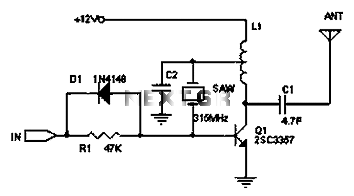
The circuit principle involves the use of an LC oscillator, which typically experiences significant frequency drift. Surface Acoustic Wave (SAW) devices have emerged as a solution to this issue, offering frequency stability comparable to that of crystal oscillators. SAW...
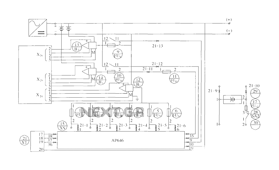
The components include B2 (13) and B3 (14) designated for the Hall current sensor; FU9 (9) and FU10 (10) serve as fuses; an AP646 alarm signal is connected to the fuse board; terminals X24, X26, and X29 function as...
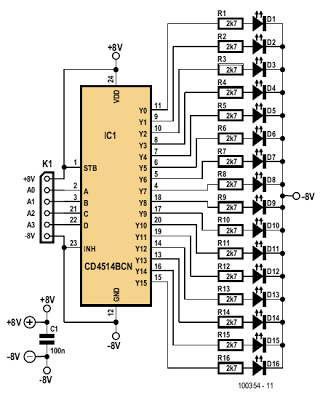
The indicator described here is specifically designed for adjusting the dynamic limiter outlined elsewhere in this edition and checking if the maximum level of the reference voltage (P1) requires modification. A 4-to-16 decoder integrated circuit (IC) of type 4514...
In all instances where Darlington transistors serve as output devices, it is crucial for the sensing transistor (Q4) to maintain close thermal contact with the output transistors. Consequently, a TO126-case transistor type was selected for ease of mounting onto...
This digital DIY tachometer for bicycles utilizes two reed switches to gather speed information. The reed switches are positioned near the wheel rim, where permanent magnets, attached to the wheel spokes, pass by and activate the switches. The speed...