
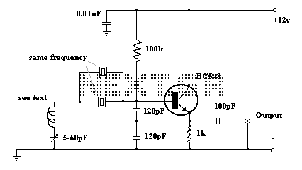
Oscillator with frequency doubled output
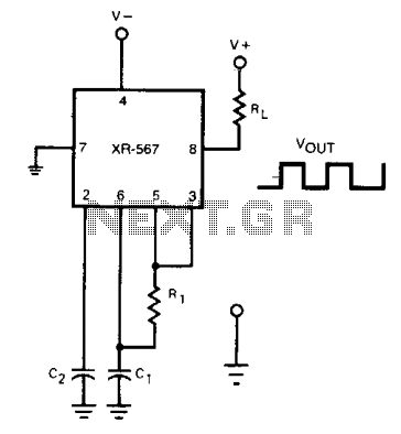
The current-controlled oscillator (CCO) operates by generating an output frequency that is dependent on an external control current. In this specific configuration, the feedback mechanism is crucial for frequency doubling. By connecting a portion of the output from pin 5 back to pin 3, the oscillator can effectively double its output frequency. This feedback creates a condition where the oscillator's output frequency becomes twice the original frequency, denoted as 2 f0.
The quadrature detector plays an essential role in this process. It is designed to detect phase differences and can thus be utilized as a frequency doubler in this application. The output from the quadrature detector at pin 8 reflects the doubled frequency, enabling various applications that require higher frequency signals.
In practical implementations, careful consideration should be given to the values of the components involved in the feedback loop, as they will influence the stability and performance of the oscillator. Additionally, the characteristics of the square-wave output must be analyzed to ensure that the feedback does not introduce unwanted harmonics or distortions that could affect the integrity of the doubled frequency output. Proper tuning and calibration of the circuit may be necessary to achieve optimal performance.The current-controlled oscillator frequency can be doubled by applying a portion of the square-wave output at pin 5 back to the input at pin 3, as shown. In this manner, the quadrature detector functions as a frequency doubier and produces an output of 2 f0 at pin 8. 🔗 External reference
Related Circuits
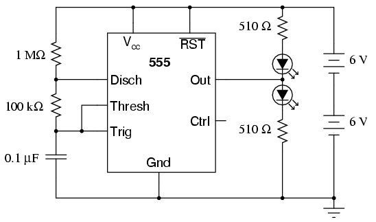
The 555 integrated circuit is a versatile timer that can be used for various applications. This experiment focuses on its operation as an astable multivibrator or oscillator. When connected to a capacitor and two resistors, it generates a square-wave...
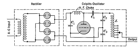
High frequencies are defined as those above 50,000 cycles per second. For industrial power supplies, the Golpitts circuit or the coupled-grid self-excited oscillator circuit is most commonly used. In either circuit, the alternating supply voltage is stepped up through...
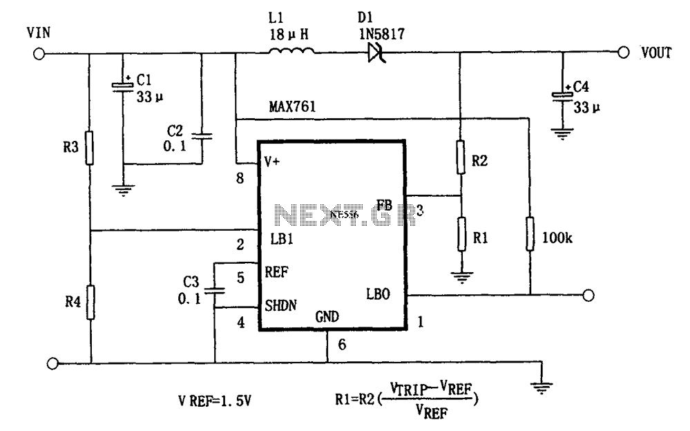
The circuit features an efficient, low-power output voltage boost DC-DC converter, MAX761, along with a few external components that facilitate adjustable power conversion. The output voltage is determined by the ratio of resistors R1 and R2, calculated using the...
The Clapp oscillator is a type of electronic oscillator constructed from a transistor or vacuum tube and a positive feedback network. The Meissner oscillator circuit is a harmonic oscillator that consists of an active electronic element, such as a...

The Wien bridge oscillator generates frequencies of 1 Hz and from 2 to 20 Hz in 2 Hz increments. The maximum output amplitude is 3 volts RMS or 8 volts peak-to-peak. A potentiometer and switch attenuator enable the output...
The circuit schematic of the UDC consists solely of dispersive components. Two low-frequency series LC resonators, with equal inductances (LA=LB) and capacitances (CA=CB), are connected to two input semi-infinite transmission lines, designated as A and B. These resonators are...
Warning: include(partials/cookie-banner.php): Failed to open stream: Permission denied in /var/www/html/nextgr/view-circuit.php on line 713
Warning: include(): Failed opening 'partials/cookie-banner.php' for inclusion (include_path='.:/usr/share/php') in /var/www/html/nextgr/view-circuit.php on line 713