
LM324 Water Level Sensor/Indicator
The hot water level indicator circuit is designed to provide a reliable method for monitoring the water level within a tank, ensuring that the operational parameters of hot water systems are maintained efficiently. The circuit typically employs a combination of sensors, such as float switches or conductive probes, to detect the water level.
In a basic configuration, the circuit may utilize a float switch that rises and falls with the water level. When the water reaches a predetermined level, the float switch activates, completing the circuit and triggering an indicator, such as an LED or a buzzer, to signal that the water level is adequate. Conversely, if the water level drops below a certain point, the switch will open, turning off the indicator and alerting the user to the low water condition.
For more sophisticated applications, conductive probes can be used to measure the water level. These probes can be placed at various heights within the tank, allowing for multiple level indications. When water contacts the probes, it completes the circuit, and the corresponding indicator activates. This method offers a more precise measurement of the water level and can be integrated with microcontrollers for automated monitoring and control.
The components required for constructing a hot water level indicator circuit typically include resistors, diodes, transistors, and the chosen sensing mechanism (float switch or probes). The circuit can be powered by a low-voltage power supply, ensuring safety and reducing energy consumption.
Overall, the hot water level indicator circuit is a practical solution for maintaining optimal water levels in various applications, from residential water heaters to industrial hot water systems, ensuring efficiency and preventing potential damage from low water levels.This is Hot Water Level Indicator circuit. This circuit can be used to monitor level of hot water in a tank. This circuit is simple and inexpensive. this.. 🔗 External reference
Related Circuits
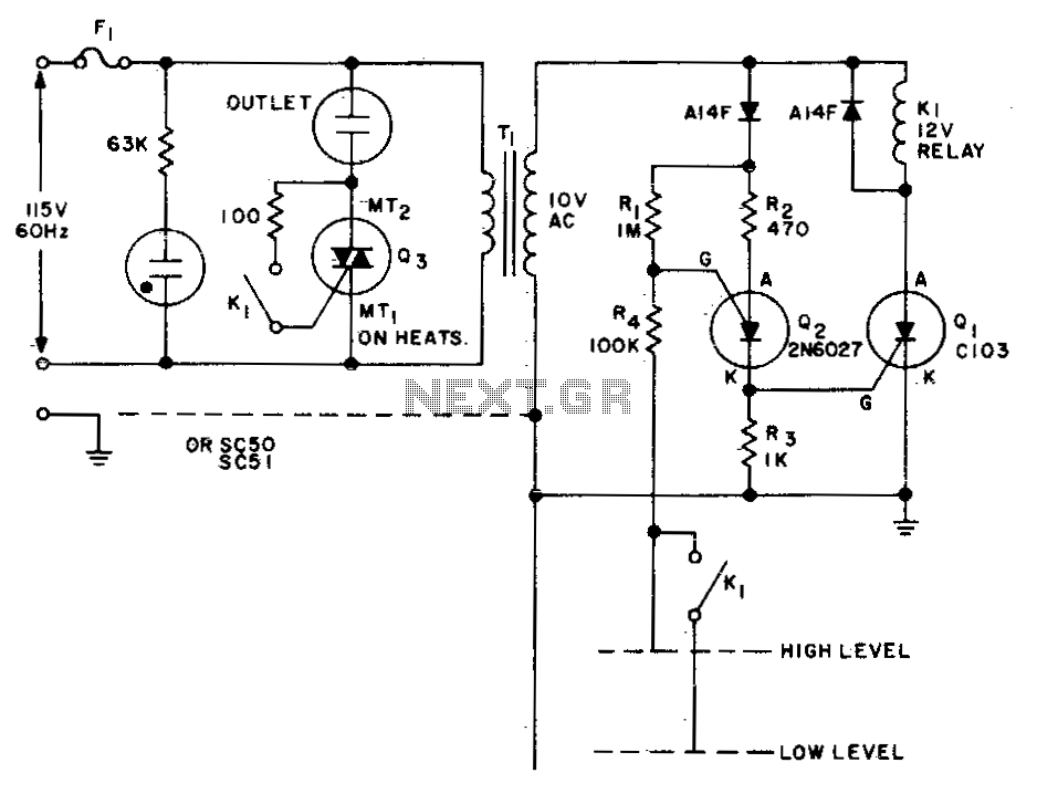
This circuit is designed to maintain the fluid level of a liquid between two predetermined points. It features two operational modes for either filling or emptying the container, which can be achieved by simply reversing the connections of relay...
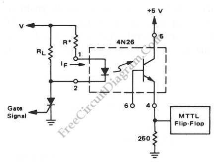
Interfacing high power loads can be accomplished in various ways, including the use of voltage divider resistors, transformers, or optocouplers. The circuit illustrated below employs the optocoupler method. This optocoupler facilitates logic level translation with flexible input, accommodating a...
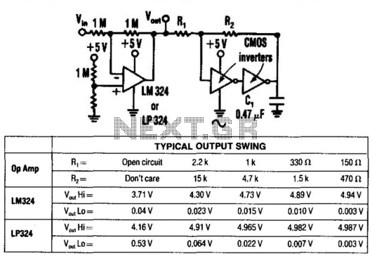
By utilizing two CMOS inverters, the output voltage of an LM324 operational amplifier can be increased from 3.5 V peak-to-peak (Vpp) to 4.9 Vpp. This circuit is recommended solely for light loads (less than 30 mA) and for relatively...
The circuit utilizes a 555 timer configured as an astable oscillator and is powered by the emitter current of the BC109C transistor. In dry conditions, the transistor does not receive bias current and remains fully off. When the probes...
The proper operation of the squelch circuit in any FM radio is essential to avoid listening to discriminator noise. This is particularly critical in a repeater system. The primary function of a squelch circuit is to detect the presence...
The following circuit illustrates a Water Level Detector Circuit Diagram. This circuit is based on the PIC12F683 microcontroller. Features include the ability of the PIC microcontroller to enter a sleep mode. The Water Level Detector Circuit utilizing the PIC12F683 microcontroller...