
lm350 car battery charger circuit design
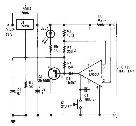
The LM350 car battery charger circuit utilizes an LM350 voltage regulator as its core component, which is known for its ability to maintain a stable output voltage and current. The circuit is designed to handle gelled lead-acid batteries, which require specific charging characteristics to ensure longevity and performance. The initial charging phase delivers a constant current of 2A, which is suitable for quickly replenishing the battery's charge.
As the battery voltage rises during the charging process, the current gradually decreases. This behavior is essential as it prevents the battery from being overcharged, which can lead to damage or reduced lifespan. Once the current falls to a threshold of 150 mA, the circuit transitions to a float charging mode, maintaining the battery at a safe voltage level without further increasing the charge.
The inclusion of transistor Q1 and LED1 provides a visual indication of the charging status, allowing users to easily monitor the process. The resistors in the circuit play critical roles in setting the current limits and ensuring the stability of the charging operation. Specifically, R2, R3, and R6 are 1-watt resistors that help manage the circuit's performance, while R7, rated at 5 watts, is capable of handling higher power dissipation.
The push-button switch serves as an interface for users to initiate the charging process, temporarily raising the output voltage to 14.5 V. This higher voltage is necessary to effectively charge the battery. As the battery approaches full charge, the circuit intelligently reduces the output voltage to around 12.5 V, ensuring that the battery is maintained in a charged state without the risk of overcharging.
Overall, the LM350 car battery charger circuit is a well-designed solution for efficiently charging gelled lead-acid batteries while incorporating safety features to protect the battery's health.This LM350 Car battery charger circuit project is a high performance charger that quickly charges gelled lead-acid batteries and turns off the charger process at full charge. This LM350 Car battery charger circuit will provide a charge current of 2A when the battery is nod fully charged, but as buttery voltage rise, current decreases.
When the current falls to 150 mA, the charger automatically switches to a lower float voltage to prevent the overcharging. When the charging process is finish the transistor Q1 make the LED1 to glow, to indicate the state of charging process.
The small value resistors R2, R3, R6 must be 1 watt resistors and R7 must be 5 watts resistors. When the push button switch is pushed, the output voltage of the charger goes to 14. 5 V and when the battery approaches to full charge, the charging current decreases and the output voltage is reduced to about 12. 5 V. 🔗 External reference
Related Circuits
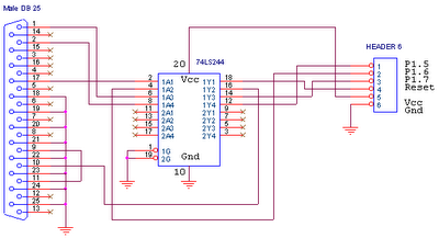
This circuit is designed for use with ATMEL Microcontroller ICs, specifically the AT89Sxx and ATMEGA series. It operates using the MISO, MOSI, SCK, and RESET signals. This circuit serves as a foundational interface for programming and communication with ATMEL microcontrollers,...
A buzzer circuit utilizes a PIC microcontroller to drive a piezo buzzer. The microcontroller is a low-power processor that is ideal for portable and compact devices where battery conservation is essential. The buzzer circuit employs a PIC microcontroller, which serves...
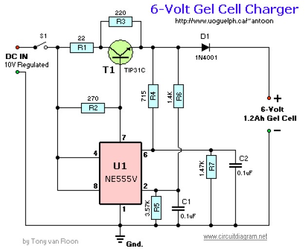
This circuit requires an adapted 10V DC power supply capable of delivering 2 Amps. It initiates the charging process at 240mA and automatically switches to a float charge (trickle charge) of 12mA when fully charged. The capacitors used should...

Transistors Q1 and Q2, along with resistors R1 through R7, form the input balancing stage that measures the resistance between points X and Y. This stage operates as a bridge circuit, incorporating resistors R1, R2, R6, R7, and the...
This circuit is designed for the selection of alternative sources. It integrates mechanical selection through a rotating switch S1, electronic control of relays RL1 to RL10, and optical indication of the selection via the display DSP1. The circuit operates by...
This page outlines the development of electronics for displaying a monochrome video image on an electrostatic oscilloscope tube. This work complements the Electron Optics section in the Experiments category. The primary objective is to showcase a moving video image...