
two transistor radio
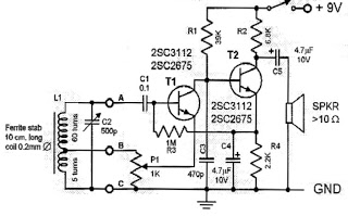
The circuit operates on a basic principle of radio frequency signal reception and processing using a single transistor to minimize component count while maximizing efficiency. The transistor, typically an NPN type, is configured in a common emitter arrangement. The input signal from the antenna is coupled to the base of the transistor via a capacitor, allowing only the AC components of the radio signal to pass through while blocking DC voltage.
The audio output is taken from the collector of the transistor, which is connected to the headphones. The series connection of the headphones ensures that the circuit remains powered as long as the headphones are connected. When the headphones are unplugged, the circuit is effectively disabled, conserving battery life.
The antenna, a simple wire of 2 meters, acts as both a signal collector and a resonant element in conjunction with the antenna coil. The coil is wound around a ferrite rod to enhance inductance and improve reception quality. The tap point at one-fifth of the total winding allows for optimal coupling of the signal to the transistor, ensuring adequate gain and sensitivity.
To further enhance performance, the circuit may incorporate additional passive components such as resistors and capacitors for biasing the transistor and filtering unwanted frequencies. The design is particularly suitable for hobbyists and educational purposes, providing a practical introduction to radio electronics and the principles of AM signal reception. This circuit can effectively receive a wide range of AM broadcasts, making it a versatile tool for exploring radio technology.Here is a simple circuit for a one transistor Audion type radio powered by a 1. 5 V battery. It employs a set of standard low-impedance headphones with the headphone socket wired so that the two sides are connected in series thus giving an impedance of 64 ©. The supply to the circuit also passes through the headphones so that unplugging the headphones turns off the supply.
Using an Audion conguration means that the single transistor performs both demodulation and amplification of the signal. The sensitivity of this receiver is such that a 2 m length of wire is all that is needed as an antenna.
The tap on the antenna coil is at 1/5th of the total winding on the ferrite rod. For details of the antenna coil see the article Diode Radio for Low Impedance Headphones. This circuit is suitable for reception of all AM transmissions from long-wave through to shortwave. 🔗 External reference
Related Circuits
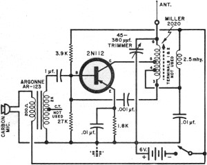
It had been a little over a decade since the invention of the transistor when this article appeared in the August 1959 edition of Popular Electronics. Transistors were still a mystery to many, including engineers, technicians, and hobbyists. Author...
Later, the same pivot table will be utilized to list the parts for each of the eight phases in the build, organizing them into phase-specific bags of parts. The initial observation is that there are slight inconsistencies between the...

The FM radio receiver circuit is designed using the TDA7000 integrated circuit (IC). This circuit operates with a DC voltage range of 2 volts to 12 volts. The TDA7000 IC is specifically engineered for FM reception and employs a...
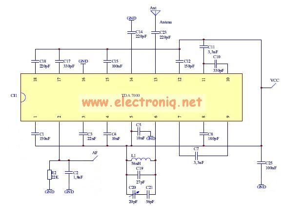
The TDA7000 features a Frequency-Locked-Loop (FLL) system with an intermediate frequency of 70 kHz, and selectivity is achieved through active RC filters. The only calibration required is for the resonant circuit associated with the oscillator, which is necessary for...
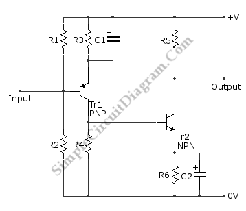
This is a directly coupled (DC) amplifier circuit. It is constructed using NPN and PNP transistors and is designed to amplify direct current (DC) signals. The directly coupled amplifier circuit utilizes both NPN and PNP transistors to achieve its amplification....
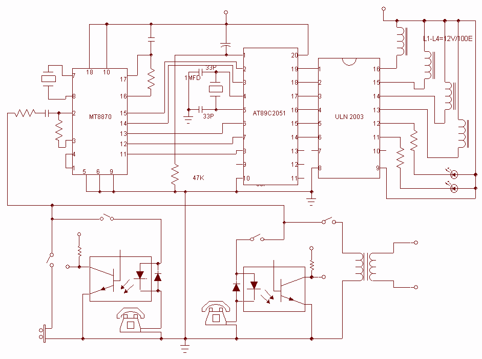
This project is used as an electronic private exchange. It has two telephones, which have the intercom facility, and they can be connected to the telephone line. All the functions are controlled by the 8-bit microcontroller AT89C2051 which has...
Warning: include(partials/cookie-banner.php): Failed to open stream: Permission denied in /var/www/html/nextgr/view-circuit.php on line 713
Warning: include(): Failed opening 'partials/cookie-banner.php' for inclusion (include_path='.:/usr/share/php') in /var/www/html/nextgr/view-circuit.php on line 713