
Logic Pulser
The LOGIC PULSER is a specialized testing device designed for diagnosing and troubleshooting digital circuits. It generates pulses of varying widths and frequencies, allowing engineers and technicians to simulate digital signals and observe circuit responses in real-time. The device is particularly effective in scenarios where traditional tools, such as multimeters or oscilloscopes, may fall short, especially in the context of testing logic states in integrated circuits.
The circuit typically consists of a pulse generator, which can be implemented using a 555 timer IC or a microcontroller, depending on the required precision and functionality. The output stage may include a transistor or a buffer to drive the pulses into the circuit under test, ensuring that the voltage levels are appropriate for the logic families being tested (e.g., TTL, CMOS).
An important feature of the LOGIC PULSER is its audible output, which provides immediate feedback to the user when a pulse is generated. This is particularly useful when testing circuits in environments where visual indicators may be difficult to monitor. The audible signal can be implemented using a simple piezo buzzer or speaker, which activates in synchronization with the pulse output.
Furthermore, the design incorporates a protection mechanism to prevent triggering when measuring across diodes, which is crucial for avoiding erroneous readings and potential damage to the device. This feature allows for safe operation in various testing scenarios, enhancing the reliability of the test results.
In summary, the LOGIC PULSER is an essential tool for anyone involved in the design, testing, or troubleshooting of digital circuits. Its ability to deliver precise pulse signals, combined with audible feedback and protective features, makes it an invaluable asset in the electronic testing toolkit.This LOGIC PULSER capable of delivering pulses of various compositions, to any type of circuit you wish to test. Basically it is designed to complement the LOGIC PROBE and can be used in situations where the LOGIC PROBE is not so effective.
It is an improvement over a multimeter in that it has an audible output and is NOT triggered when measuring across a diode. Don`t underestimate the importance of this item of test equipment. It is needed to properly test and locate a fault in digital circuits. The time when you appreciate it most is when a tricky fault comes along. We have had a number of these and know how difficult it is to improvise. A multimeter and CRO are all right for some applications but when it comes to testing digital circuits, the 🔗 External reference
Related Circuits
This mini logic analyzer is a tool that allows users to observe the logic transitions (0 or 1) of a digital data signal on an LCD display. Such digital data signals can be found on the output pin of...
This project is a combination Logic Probe and Logic Pulser. It is capable of testing all sorts of digital and microcomputer projects. You will find it extremely handy when designing a project as the golden rule is to test...
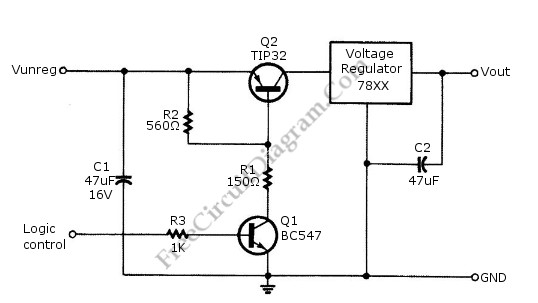
Logic power control of an analog regulator can be useful in applications where a digital circuit or controller needs to manage a power source, such as in EEPROM programmers or other power control systems. This circuit provides ON-OFF control...
The circuit diagram illustrates a five-use tri-state audio logic pen utilizing components such as the CD4066 and a 555 timer. The primary elements include a multivibrator, a four-way switch (CD4066, designated as IC1), and a gate circuit formed by...
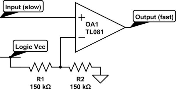
Invert a signal to drive FETs with rapid rise and fall times. It was suggested to use an inverter (not a chip) instead of logic chips, which are designed to be either fully ON or OFF. The individual has...

The schematic below illustrates four methods of controlling a relay with a digital logic signal. Figure A can be used in most cases where the relay coil requires 100 mA or less and the input current is 2 milliamps...