
Long duration timer
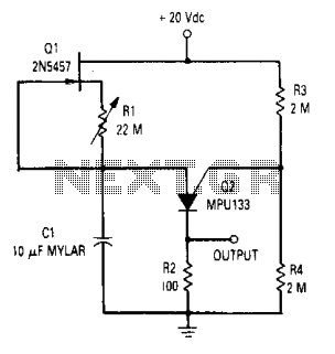
The described time circuit functions as a delay mechanism, capable of producing a time interval of up to 20 minutes. It operates as a relaxation oscillator, a common configuration in timing applications, utilizing a Field Effect Transistor (FET) as a current source. The circuit's design incorporates a resistor, designated as R1, which is crucial for establishing a reverse bias condition on the gate-to-source junction of the Junction FET (JFET). This reverse bias effectively turns the JFET off, thereby extending the charging time of the capacitor C1.
C1 is specified to be a low leakage capacitor, with mylar capacitors being recommended due to their favorable characteristics in timing circuits. Mylar capacitors are known for their stability and low leakage current, which is essential in maintaining the integrity of the timing interval. The combination of the FET, resistor R1, and capacitor C1 creates a time constant that governs the delay duration.
In the operation of the circuit, when power is applied, C1 begins to charge through the FET. The time taken for C1 to reach a specific voltage level, determined by the circuit's design, will dictate the delay before the output signal is activated. The relaxation oscillator mechanism contributes to the repetitive nature of the timing cycle, allowing for consistent and reliable operation. The values of R1 and C1 can be adjusted to fine-tune the time delay, providing flexibility in various applications where precise timing is required.The time circuit can provide a time delay of up to 20 minutes. The circuit is a standard relaxation oscillator with a FET current source in which resistor Rl is used to provide reverse bias on the gate-to-source of the JFET. This turns the JFET off and increases the charging time of Cl. Cl should be a low leakage capacitor such as a mylar type. 🔗 External reference
Related Circuits
Most supermarkets today offer plug-in mains-powered digital programmable timers. These devices are designed to automatically turn lights on and off, activate washing machines while the user is away, and more. Prices start at around £5 ($10), and these products...
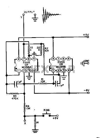
This simple bell circuit utilizes two 555 timers. The frequency is regulated by capacitors that should maintain nearly identical values for optimal performance. Fine-tuning is achieved using resistors R1 and R2. Additionally, the decay time is managed by resistor...

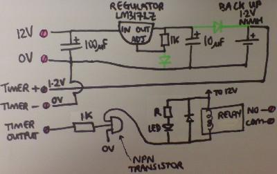
This circuit is designed as a countdown timer utilizing a countdown calculation. It employs the 555 integrated circuit (IC) as the primary control element. The 555 IC functions as a counter and a transistor switch to activate a relay...

The power output of most of these circuits is very low because no power amplifier stages were incorporated. The transmitter circuit described here includes an additional RF power amplifier stage, following the oscillator stage, to increase the power output...
The SC9256 is a phase-locked loop (PLL) integrated circuit designed for digital tuning systems (DTS), featuring built-in 2 modulus prescalers. All functions are controlled through three serial bus lines. These integrated circuits are utilized to configure high-performance digital tuning...
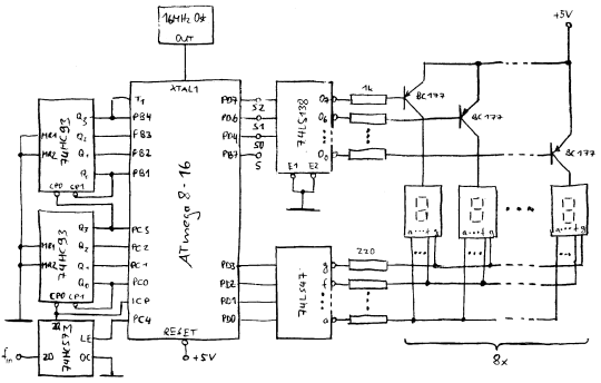
In counter mode, it provides 1 Hz resolution up to 100 MHz. In timer mode, the maximum resolution is 0.0000001 Hz up to 1 Hz. The resolution decreases by one digit for each additional decade. Multiple frequency updates per...