
Long duration timer with Attiny2313

No description available.
Related Circuits
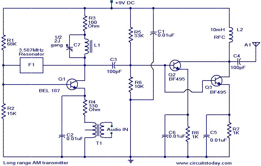
The circuit diagram of an AM transmitter circuit based on three transistors. With correct tuning and a matching antenna, the transmitter can effectively transmit amplitude-modulated signals. The AM transmitter circuit utilizes three transistors configured to amplify and modulate the input...
The following schematic diagram is a four-hour timer circuit. Features include ease of construction, a total timing duration of 3 hours and 53 minutes, and a 9V supply voltage. Components utilized in the circuit are a 555 timer IC,...
The electromagnetic RBI timer features a simple structure, is cost-effective, and is commonly utilized in high school physics experiments. However, a significant drawback of the electromagnetic RBI timer is the substantial errors it produces during experiments. This issue arises...
A 100 second delayed turn ON relay RL1 switch, if plug power +12V in circuit. In Fig.2 see a two range 6-60 second and 1-10 minute auto turn off relay timer circuit, with 555. Part List R1=1 Mohms C4=100nF...
This simple alarm timer circuit is constructed using a 4060 integrated circuit, which features a stable oscillator with a relatively wide frequency range. The alarm timer circuit utilizes the CD4060 IC, which combines a low-frequency oscillator and a binary counter....
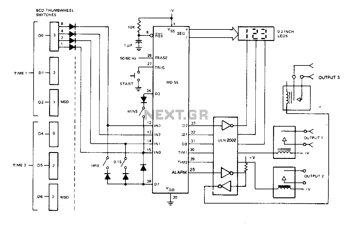
The device is a switch programmable on/off or interval timer that features three relay-switched outputs. Output one activates for the duration of time one, output two activates for the duration of time two, and output three activates for the...