
Thumbwheel programmable interval timer
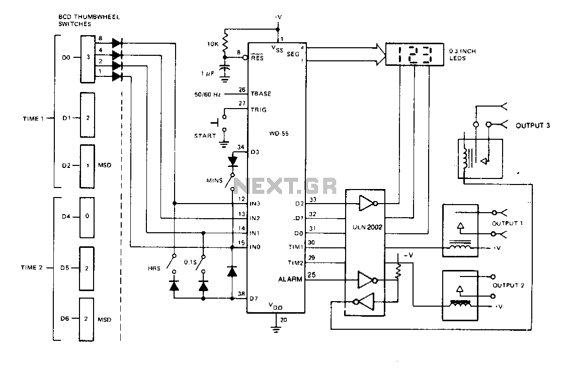
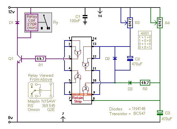
The programmable timer circuit operates by utilizing a microcontroller that processes the input from the six BCD-encoded thumbwheel switches. Each thumbwheel switch corresponds to a specific digit in binary-coded decimal format, allowing for precise timing settings ranging from seconds to hours. The three SPST switches serve as mode selectors, enabling the user to define whether the input timing is interpreted as seconds, minutes, or hours.
The microcontroller's firmware is designed to interpret the BCD inputs and convert them into a time duration that controls the relay outputs. The three relay-switched outputs are operated based on the programmed durations, allowing for sequential or simultaneous activation of connected devices. The first output is activated for the time set by the first thumbwheel switch, the second output for the duration set by the second thumbwheel switch, and the third output remains active for the total duration of both the first and second outputs.
An integral part of the circuit is the LED display, which provides real-time feedback on the countdown process. During operation, the display shows the time remaining until the next relay activation, enhancing user interaction and control. The design eliminates the need for battery backup due to the nonvolatile nature of the data input via the thumbwheel switches.
In summary, the circuit is designed for reliability and ease of use, providing a versatile solution for timing applications without the complications of volatile memory or battery dependence. This programmable timer is suitable for various applications, including automation systems, industrial controls, and home automation projects.Switch programmable on/off or interval timer, has three relay-switched outputs. Output one is active for the duration of time 1, output two is active for the duration of time 2, and output three is active for the duration of both one and two. Timing data is input through 6 BCD-encoded thumbwheel switches. Three SPST switches inform the WD-55 to interpret this data as NNN seconds. NNN seconds, NNN minutes, or NNN hours The LED display will show the time remaining and the countdown when operating. Since the data is input through switches, the display may be deleted. Also, since the timing information is read from switches, the data is nonvolatile and no battery backup is required. 🔗 External reference
Related Circuits
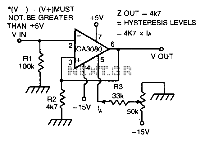
The CA 3088 is utilized as a versatile Schmitt trigger. The magnitude of the hysteresis levels is determined by the current (Ia) flowing out of the amplifier's output and through resistor R2. An increase in Ia results in an...
The crime prevention bell device produced approximately 20 years ago remains in active service. It has effectively deterred thieves on multiple occasions by triggering an alarm as they attempt to enter. The bell continues to ring, functioning as a...
This circuit provides a visual 9-second delay using 10 LEDs before closing a 12-volt relay. When the reset switch is closed, the 4017 decade counter is reset to the 0 count, illuminating the LED driven from pin 3. The...
This timer utilizes a basic monostable circuit. The duration for which the relay remains energized, referred to as the ON period, is regulated by the resistor R3 and capacitor C2. Conversely, the duration for which the relay remains de-energized,...
This timer was designed for people wanting to get tanned but at the same time wishing to avoid an excessive exposure to sunlight. A Rotary Switch sets the timer according to six classified Photo-types (see table). A Photo resistor...
This circuit illustrates the NE555 timer used in a light-sensitive alarm sensor circuit diagram. Features include the ability to detect a sudden shadow falling on the sensor. The NE555 timer is a versatile integrated circuit widely utilized in various timing,...