
Long-Interval Programmable Timer

The described circuit employs a resistor-capacitor (RC) oscillator to generate a low-frequency signal suitable for timing applications. The RC oscillator's frequency is determined by the values of the resistors and capacitors in the circuit. In this case, R2 and R4 are configured to establish the timing interval, while C2 provides the necessary capacitance for oscillation. The oscillator output feeds into a 24-stage ripple counter, which is capable of counting up to 16,777,216 (2^24) clock pulses.
The ripple counter operates by incrementing its count with each clock pulse received from the oscillator. At a count rate of 0.1 Hz, the counter will take approximately 654 seconds to complete a full cycle, demonstrating its utility in applications requiring long-duration timing. The MC14536 timer, a versatile integrated circuit, is utilized to manage the timing functions effectively.
For applications requiring even longer time intervals, adjustments to the RC oscillator can be made, such as increasing the resistance or capacitance values, or employing additional stages in the counter. This flexibility allows for the design of timing circuits that can cater to various operational needs, making it a valuable component in digital timing applications across multiple fields. Using an RC oscillator, an up to 24-stage ripple counter O) 16777216 or 2U, and a 0.1-Hz count-rate with # 2 = 39 KOhm, C2 = 0.001 ¥, and R4=220 KOhmhm for example, the count cycle would take about 654 s. This example shows the capabilities of this time circuit, using the Motorola MC14536 timer. A low-frequency oscillator can be used for longer time periods.
Related Circuits
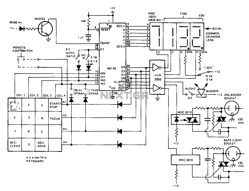
The darkroom timer/controller utilizes a minimal number of external components, including a display, a digit driver, a keyboard, and output switching devices. A 4-digit common-cathode LED display is preferred for use in darkroom settings. The time base is generated...
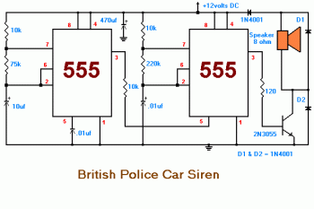
This circuit displays a sound generator that simulates the siren of a British police car. The circuit is constructed using two timer IC 555. The sound generator circuit designed to simulate a British police car siren utilizes two 555 timer...

The circuit below demonstrates the generation of a single positive pulse that is delayed in relation to the trigger input time. It is similar to a previously described circuit but utilizes two stages, allowing for control over both the...
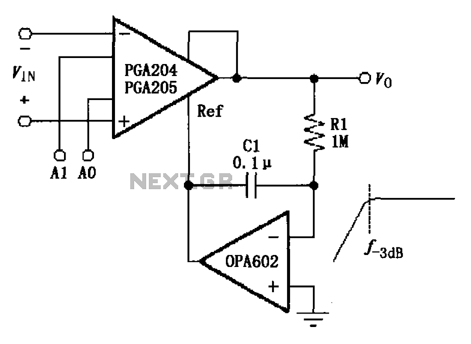
The circuit depicted in the figure features a programmable amplifier utilizing the PGA204/205 operational amplifiers in conjunction with the OPA602. The OPA602 op-amp is configured to establish a feedback reference point, while external components, specifically the capacitor C1 and...
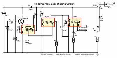
Timer garage door circuit schematic diagram, printed circuit board. The timer garage door circuit is designed to automate the opening and closing of a garage door based on a predetermined time interval. The schematic diagram illustrates the layout and connections...
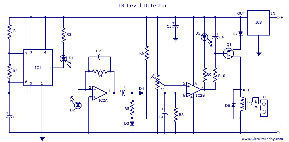
The circuit illustrates the use of a 555 Timer IC in an infrared (IR) detector configuration. It features a duty cycle of 0.8 milliseconds, a frequency of 120 Hz, and a peak current of 300 mA. The 555 Timer IC...