
piclink rs232 low cost development controller with adc using pic16f628a

The PICLink RS232 embedded controller is designed to facilitate communication between microcontrollers and RS232 devices, making it an essential component for various embedded applications. This module incorporates an Analog-to-Digital Converter (ADC), enabling it to process analog signals and convert them into digital form for microcontroller interfacing.
The design typically includes a microcontroller unit (MCU) that manages the RS232 communication protocol, ensuring reliable data transmission and reception. The RS232 interface is widely used for serial communication, characterized by its simplicity and effectiveness over short distances. The module is equipped with standard connectors for easy integration into existing systems.
In addition to the RS232 interface, the inclusion of an ADC allows the module to handle a variety of input signals, making it suitable for applications that require sensor data acquisition. The ADC's resolution and sampling rate are critical parameters that determine the fidelity of the analog signal representation.
Power supply requirements for the PICLink RS232 module are generally modest, often operating within a range of 5V to 12V, depending on the specific design. Proper voltage regulation and decoupling capacitors are essential to ensure stable operation and minimize noise interference.
Overall, the PICLink RS232 low-cost development controller is a versatile solution for engineers and developers seeking to implement serial communication in their embedded systems while also providing the capability to interface with analog sensors through its ADC functionality.PicLink RS232 low cost development controller with ADC PICLink RS232 Embedded Controller The PICLink RS232 controller module affords any microcontroller en.. 🔗 External reference
Related Circuits
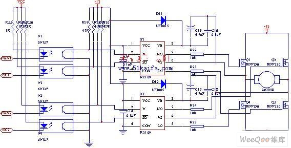
The drive circuit for the electromotor comprises a FET bridge circuit, a FET base drive circuit, a current sensor for the motor drive circuit, and a relay. The FET bridge circuit primarily consists of four high-power MOSFETs, which must...

The 10A H-Bridge Motor Controller circuit appears straightforward, but several critical aspects should not be overlooked. The primary components utilized in the circuit include the TIP147, TIP142, and 2N2222 transistors. The power supply circuit operates at +12V, which is...
It is very interesting and convenient to be able to control everything while sitting at your PC terminal. Here, a simple hardware circuit and software is used to interface a 7-segment based rolling display. The printer port of a...
This amp delivers a lot of power and uses 1 IC and two power transistors. The circuit consists of an amplifier IC (a TDA 2030A) and a power stage consists of two transistors. The amplifier can be powered with...
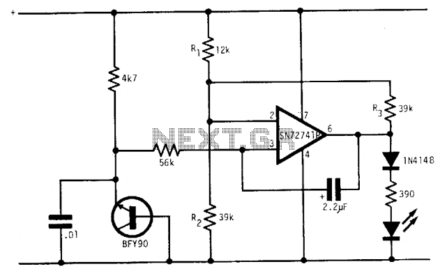
Under optimal battery conditions, the LED remains off. As the battery voltage decreases, the LED starts to flash, and when the battery reaches a low voltage condition, the LED illuminates continuously. This circuit is designed for use with a...
The simplest form of motor controllers, apart from a basic on/off switch, is the contactor controller. This contactor controller is recommended for use in electric scooter projects. It is based on three 12V relays, two 12V batteries, two switches,...