
Loudspeaker Protection
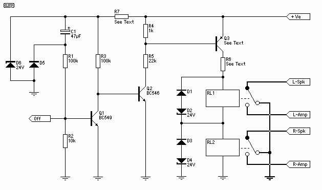
The described detector circuit is designed to effectively identify and respond to DC offsets while maintaining immunity to low-frequency signals and asymmetrical waveforms. The circuit's operation is characterized by its ability to remain inactive when subjected to a 30V RMS signal at a frequency of 5Hz, indicating a robust filtering mechanism that prevents false triggering from low-frequency AC signals.
Upon application of a DC voltage, the circuit demonstrates a response time of 60 milliseconds when a 30V DC supply is used, and a slightly faster response of 50 milliseconds with a 45V DC supply. This rapid response is crucial for applications requiring timely detection of DC offsets. The use of a non-polarised electrolytic capacitor in the filter design is particularly advantageous, as it allows for cost-effective and compact circuit solutions. These capacitors are well-suited for this application due to their small size and adequate performance in filtering tasks.
The primary function of the circuit is to detect DC offsets of both polarities, ensuring versatility in various applications. The design aims to eliminate sensitivity to asymmetrical waveforms, which is a common challenge in signal detection circuits. This capability is essential for reliable operation in environments where signal integrity may be compromised by noise or distortion. The simplicity of the circuit design enhances its reliability and ease of implementation, making it an ideal choice for a variety of electronic applications that demand efficient DC detection without the complications introduced by complex circuitry.The detector circuit shown in Figure 1 (1) is simple and works well, and as shown will not trigger with a 30V RMS signal at 5Hz, but operates in 60ms with 30V DC applied, and in 50mS with a 45V DC supply. This should be sufficient for most applications, and allows the use of a non-polarised electrolytic capacitor in the filter.
These are cheap, small and quite adequate for this purpose. This is the most important of the functions. It must be capable of detecting a DC offset of either polarity, and be immune to the effects of asymmetrical waveforms and low frequencies. This is a common requirement, and it is most expedient to use a simple 🔗 External reference
Related Circuits
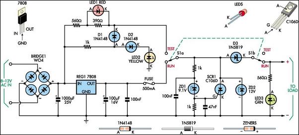
This 8V DC power supply is designed for use with high-end electronic equipment. It includes full over-voltage protection to safeguard against regulator failure, whether in the supply itself or in the connected device. The circuit employs a standard full-wave...

A simple 5 Volt regulated power supply unit (PSU) featuring overvoltage protection. This 5 Volt regulated power supply is designed for TTL and 74LS series integrated circuits. The 5 Volt regulated power supply unit is an essential component in electronic...
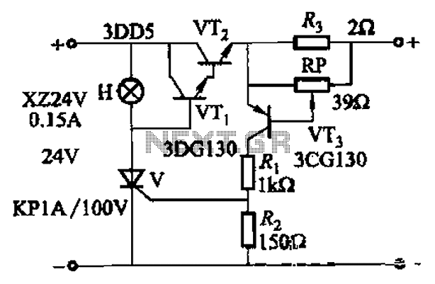
By adjusting Ro or RP, the current setpoint can be modified. The circuit illustrated in Figure 14-98 features overcurrent protection using a thyristor and transistors VTi and VT2, which immediately cut off the power when an overcurrent condition is...
That circuit protects the overdriven signals going into an amplifier. Instead of a zener diode, we use a transistor. That way we ensure that the above the ordinary input voltages (1 volt r.m.s.) can be achieved without distortion. Also,...
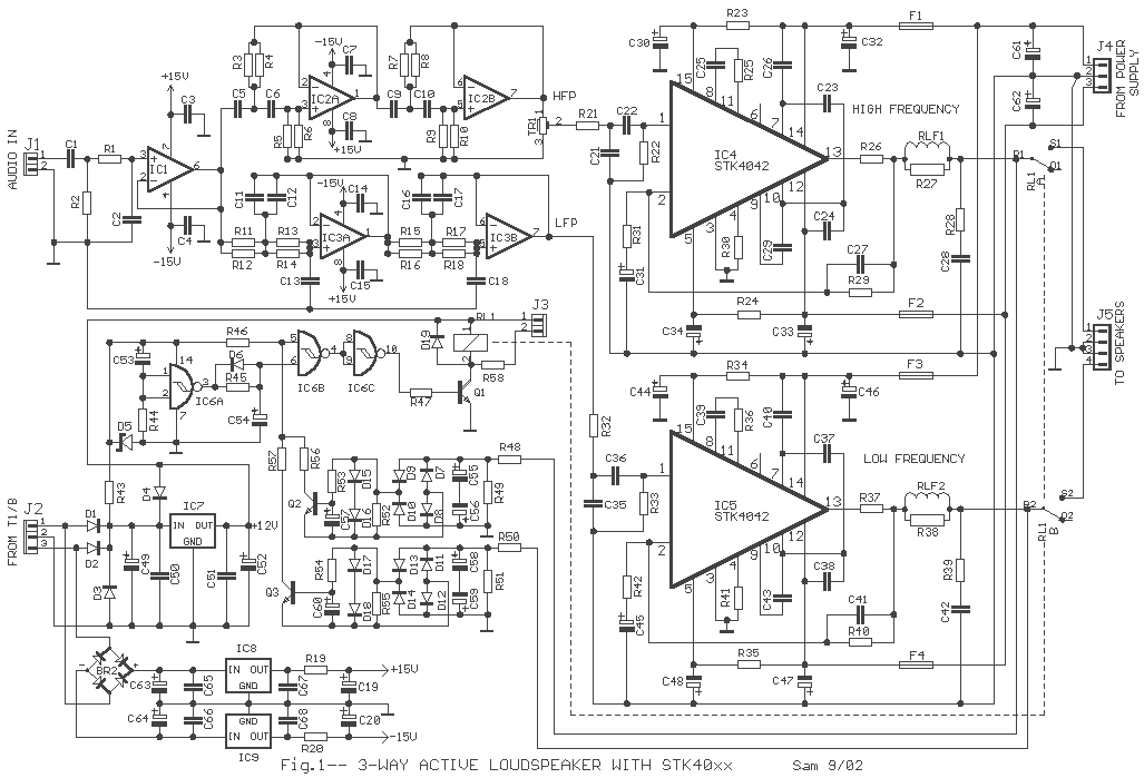
Active loudspeakers have a lot of advantages concerning simple loudspeakers that use passive components for the elements concretisation of segregation of frequencies. In the case of active loudspeakers we have, proportionally, bigger build cost, because each loudspeaker is led...
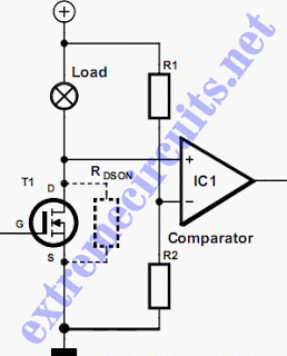
In applications where a MOSFET is employed to switch a load, incorporating short-circuit or overload protection is straightforward. This can be achieved by utilizing the internal resistance RDS(ON) of the MOSFET, which generates a voltage drop proportional to the...