
Desheng 1012 12-band television sound radio circuit diagram
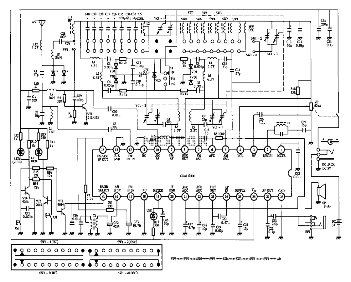
The Desheng 1012 radio circuit is designed to receive a wide range of frequencies across multiple bands, including FM (Frequency Modulation), MW (Medium Wave), SW (Short Wave), and TV sound. This versatility allows the user to access various audio content from different broadcasting services.
The circuit typically includes several key components: a tuner for frequency selection, amplifiers to boost the received signals, and demodulators to convert the modulated signals back into audio. The 12-band feature indicates that the radio can be tuned to 12 distinct frequency ranges, enhancing user experience by providing a broader selection of stations.
The FM band is primarily used for music and entertainment, while the MW band is commonly used for talk radio and news. The SW band allows for long-distance broadcasts, often featuring international stations, and the TV sound band enables reception of audio from television broadcasts.
In the schematic, the tuner section may utilize variable capacitors or inductors to adjust the frequency, while the amplifier sections typically consist of operational amplifiers or transistors configured for audio amplification. The demodulation process may employ a simple envelope detector or more complex methods depending on the design requirements.
Overall, the Desheng 1012 circuit diagram represents a comprehensive design that facilitates multi-band reception, providing users with a versatile radio experience. Proper implementation of the components as per the schematic will ensure optimal performance and sound quality across all selected bands.Desheng 1012 12-band FM, MW, SW, TV sound radio circuit diagram as follows:
Related Circuits
This document outlines a simple PWM (Pulse Width Modulation) DC to AC voltage inverter circuit based on the SG3524 integrated circuit. The SG3524 is a fixed frequency PWM voltage regulator control circuit that offers indifferent outputs suitable for both...
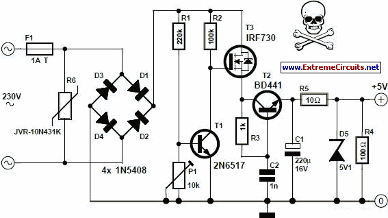
An increasing number of appliances draw a very small current from the power supply. If designing a mains-powered device, one can generally choose between a linear and a switch-mode power supply. However, when the appliance's total power consumption is...

This circuit is capable of generating up to 1 W of audio power to drive a speaker or horn. When the CDS cell is exposed to light, its resistance decreases, activating NOR gate (a). This activation causes gates (a)...

The FM radio receiver circuit is designed using the TDA7000 integrated circuit (IC). This circuit operates with a DC voltage range of 2 volts to 12 volts. The TDA7000 IC is specifically engineered for FM reception and employs a...
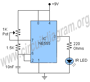
This schematic illustrates an infrared (IR) transmitter circuit utilizing an integrated circuit (IC). The circuit employs the widely recognized NE555 timer IC, which operates as an astable multivibrator to generate a signal with a frequency of 38 kHz. The...
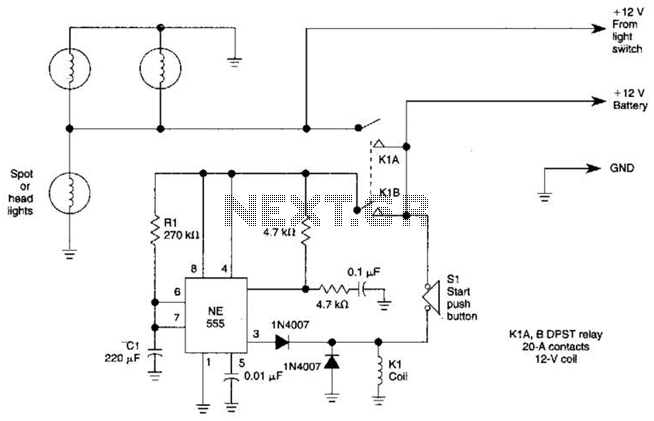
Pressing the START pushbutton activates either the headlights or spotlights for a specified duration. After 1 minute, determined by R1 and C1, the lights will turn off as the NE555 timer completes its cycle. The circuit utilizes a NE555 timer...