
Low-Cost Barometer
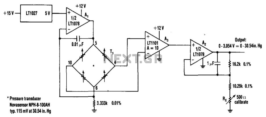
The circuit utilizes the LT1027 precision voltage reference to provide a stable reference voltage for the LT1078 operational amplifier. The LT1078 is configured to amplify the output signal from the pressure transducer, T1, which operates at a current of 1.5 mA. The transducer generates a small voltage signal that corresponds to the pressure it measures. To ensure that this signal is suitable for further processing, it is necessary to amplify it.
The gain of the amplifier is set to 10, which means that the output voltage will be ten times the input voltage from the transducer. This is achieved by configuring the feedback and input resistors of the LT1078 in accordance with the standard non-inverting amplifier configuration. Following the amplification stage, a voltage follower (also known as a buffer) is implemented to isolate the amplifier from the load. The voltage follower is configured using another LT1078 op-amp, ensuring that the output voltage remains unchanged while providing high input impedance and low output impedance.
The final output from the voltage follower can be directed to either an analog meter or a digital voltmeter (DVM) circuit. The choice of output device depends on the application requirements. An analog meter provides a visual representation of the pressure reading through a moving needle, while a DVM offers a digital display that can provide more precise readings. The circuit design ensures that both output options can be utilized without the need for additional components, making it versatile for various measurement applications. Using Linear Technology LT1027 reference and LT1078 op amps, transducer T1 is fed with 1.5 mA. The pressure transducer f eeds an amplifier with a gain of 10, then it feeds a voltage follower. Output can either drive an analog meter or a DVM circuit. 🔗 External reference
Related Circuits
The MAX5953A offers a straightforward, cost-effective, and comprehensive non-isolated power integrated circuit (IC) solution for Powered Devices (PD) in Power-over-Ethernet (PoE) systems. The MAX5953A is designed to facilitate the implementation of Power-over-Ethernet applications by providing an efficient means of...
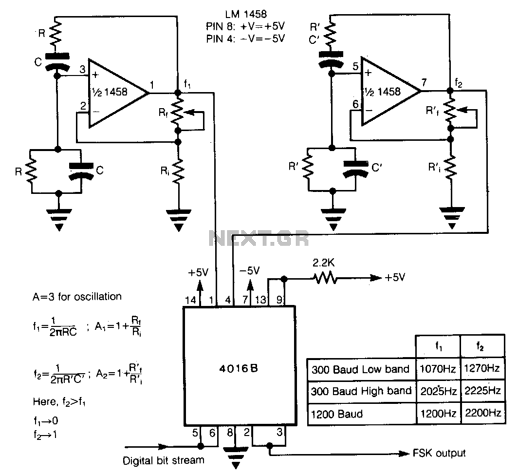
In Frequency Shift Keying (FSK), two distinct frequencies are utilized to represent the binary digits 0 and 1. The core of the circuit comprises two Wien-bridge oscillators constructed with a dual operational amplifier LM1458, each generating one of the...
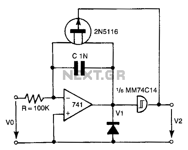
The 741 operational amplifier integrator signal is input into the Schmitt trigger of an inverter. When the signal reaches the positive-going threshold voltage, the inverter's output switches to zero. This output directly controls the FET switch. With a gate...
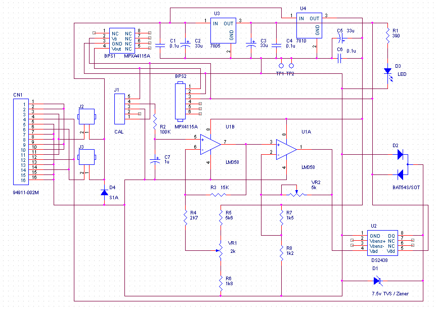
The resolution of the barometric pressure is approximately 0.00417 inHg (0.0139 kPa) within a pressure range of 31.0 to 28.0 inHg (105.0 to 95.0 kPa, or 1050 to 950 mb or hPa). Higher resolutions can be achieved with a...
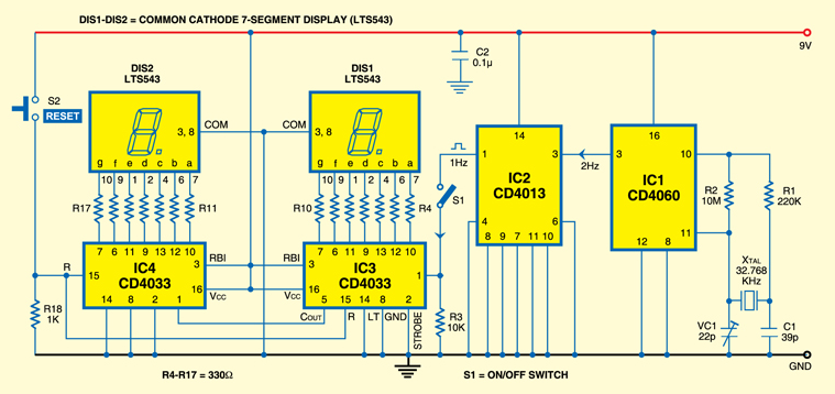
A simple stopwatch circuit that can count up to 99 seconds. The circuit utilizes CD4060, CD4013, CD4033, LTS543, and several discrete components. A crystal-controlled oscillator generates 1Hz pulses using a 32.768kHz miniature crystal. The CD4060 (IC1) features a 14-bit...
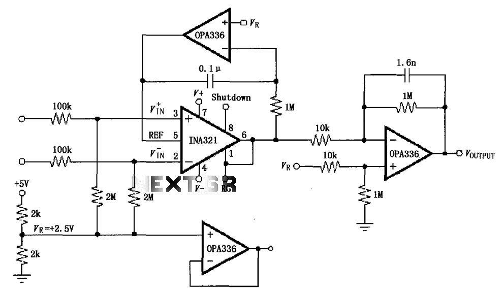
The INA321/322 forms a low-cost, medium-accuracy ECG amplifier circuit. The INA321 receives input signals from the patient's arm, amplifying them before sending the modified output to the operational amplifier OPA336. The OPA336 generates an output voltage from the inverting...