
Low Cost Battery Condition Indicator
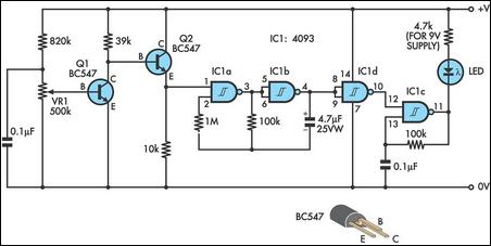
The schematic for this design includes several key components that work together to achieve the desired functionality. The core of the circuit is the 4093 CMOS quad Schmitt NAND IC, which is utilized to create two distinct oscillators: a high-frequency oscillator for the power-on indication and a low-frequency oscillator for the low-battery indication.
The high-frequency oscillator is configured using one gate of the 4093 (IC1c) and is responsible for pulsing the LED at a frequency of at least 50Hz. This creates the illusion of a steady light while minimizing power consumption. The LED's current-limiting resistor can be calculated based on the supply voltage and the desired LED current, ensuring safe operation across various battery voltages.
The low-battery indication circuit is activated when the voltage at the base of Q1 drops below 0.6V. This transistor acts as a switch, controlling the state of Q2, which in turn enables the second oscillator (IC1a and IC1b) to pulse at 1Hz. The output from this oscillator is fed into IC1d, which inverts the signal to modulate the LED's operation, indicating low battery status through a slow pulsing effect.
For calibration, the circuit can be tested with a variable power supply. By adjusting VR1, the threshold at which the low-battery indication activates can be fine-tuned to the desired voltage level, ensuring accurate performance. This design provides a practical solution for battery-operated devices, combining efficient power management with clear visual indicators for both operational status and battery health.This design combines power-on and low-battery indication, can operate with any battery voltage up to 15V, has very low current drain (2mA or less) and costs less than $3. 50 with new parts. When the battery voltage is above a predetermined minimum, power on is indicated by what appears to be a steadily lit LED.
In fact, the LED is being pulsed by a free-running relaxation oscillator formed by IC1c, one gate of a 4093 CMOS quad Schmitt NAND. The frequency of this oscillator should be at least 50Hz, so that it appears to be continuously on while at the same time drawing far less average current than a steadily lit LED. The series resistor for the LED needs to be selected for each battery voltage, to limit the current to a safe vale or you could use a fixed resistor and a series trimpot for flexibility.
Low battery voltage is indicated by the LED pulsing at around 1Hz. The battery voltage is monitored by transistor Q1 and trimpot VR1. Once the voltage at its base falls below 0. 6V, Q1 turns off and Q2 turns on to enable the 2-gate oscillator formed by IC1a and IC1b, which runs at 1Hz. The pulses from this oscillator are inverted by IC1d to gate the LED oscillator on and off. Calibration can be done with a variable bench power supply set to the lowest battery voltage you will accept.
Power up the circuit and adjust VR1 until the LED pulses once per second. 🔗 External reference
Related Circuits
Improved Vibrating Battery Tester. This circuit is based on the LM393 integrated circuit. Features include the ability to test AAA, AA, C, and D cells. The Improved Vibrating Battery Tester utilizes the LM393, a dual comparator IC, to accurately assess...
All miniature electronic devices operate off batteries. Some of them require higher than the standard battery voltages to function efficiently. Miniature electronic devices, which include a wide range of applications from portable gadgets to remote sensors, typically rely on battery...

Protect expensive batteries from discharge damage with this mini-sized electronic cutout switch. It consumes minimal power and can be adapted to accommodate a wide range of battery voltages. In May 2002, Silicon Chip introduced the "Battery Guardian," a project...
To modify the servomotors, first remove the four screws securing the servo casing and disassemble it completely. Carefully extract the electronic components while retaining only the wiring. Modifying servomotors involves a systematic approach to disassembly and reconfiguration of the internal...
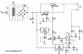
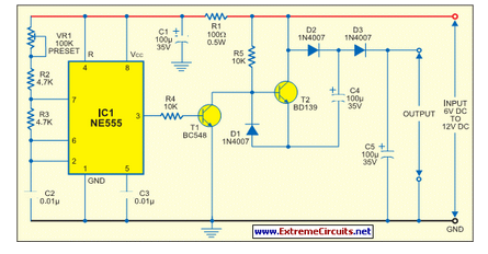
This battery charger circuit is regulated and adjustable, enabling it to charge most NiCAD batteries. It can accommodate both single cells and multiple battery cells connected in series or parallel. The maximum voltage of the batteries should not exceed...
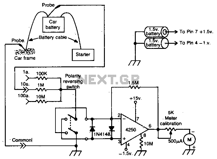
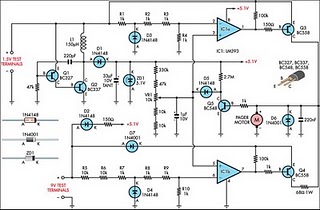
This operational amplifier (op-amp) analyzer is designed to measure the current drawn by any device in a vehicle. It operates by detecting the minute voltage that develops across the battery cables when current flows. To calibrate the unit, the current...