
Low cost light dimmer using an SBS and triac
The described light dimmer circuit employs a silicon-controlled rectifier (SCR) in conjunction with a triac to control the brightness of incandescent lamps. The primary function of the triac is to regulate the power delivered to the load by controlling the phase angle of the AC supply voltage.
In this circuit, the SCR is shunted by two 20K ohm resistors. This configuration serves to mitigate the flash-on effect, which is a common issue in light dimming applications where the load may briefly illuminate at full brightness when the circuit is activated. The use of two resistors in parallel effectively reduces the overall resistance seen by the SCR, allowing it to trigger more reliably and preventing the sudden surge of current that causes the flash-on effect.
The operation of the dimmer relies on the principles of phase control. By adjusting the trigger point of the triac, the circuit can vary the amount of time the load is energized during each half-cycle of the AC waveform. This is typically achieved using a variable resistor or potentiometer that alters the gate trigger signal to the triac.
The circuit can be designed to include additional components such as capacitors and diodes for further stabilization and to protect against voltage spikes, which can be detrimental to the SCR and triac. Proper heat sinking for the SCR and triac is also essential to ensure reliable operation, as these components can generate significant heat under load conditions.
Overall, this low-cost light dimmer circuit is suitable for various lighting applications, offering a practical solution for adjusting light levels while minimizing unwanted effects associated with traditional dimming methods.Low-cost light dimmer using an SBS and triac. Shunting the SBS with two 20K resistors minimizes the flash-on effect, courtesy Motorola Semiconductor Products Inc. 🔗 External reference
Related Circuits
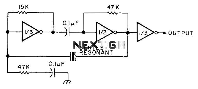
The circuit diagram illustrates the connection of all three components of the series resonant crystal and triple CD4049 inverter. The supply voltage range is between 3 to 15 volts, making it suitable for various applications. This design is compact...
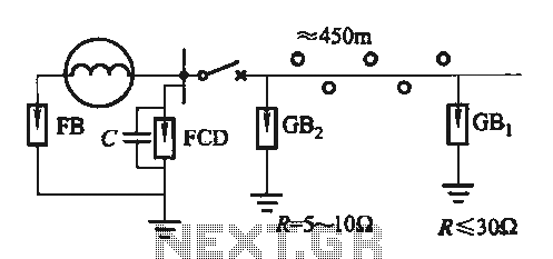
Direct distribution lightning generator with a capacity range of 300 to 1500 kW, designed for single-phase applications. The generator facilitates the direct distribution of electrical energy, providing reliable performance for various applications. The lightning generator operates within a specified power...
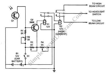
Automatic headlight dimmer circuit diagram for a car's headlight. This circuit ensures maximum brightness for optimal visibility while automatically switching when necessary. The automatic headlight dimmer circuit is designed to enhance driving safety by adjusting the brightness of the vehicle's...
The thermostat can be set, and it specifies the lower limit of the circuit diagram. The thermostat in the circuit is a critical component used to regulate temperature by controlling the heating or cooling system. It operates by comparing the...
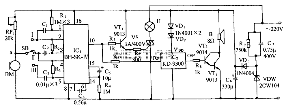
The circuit includes a microphone transducer, voice circuits, an SCR control circuit, a vocal music buck rectifier circuit, and an AC circuit. The BH-SK-IV serves as the core of the device. The described circuit is a complex assembly designed to...
This circuit can generate a voltage of 15V. In this circuit, the LM340 input voltage must remain within the limits specified in the data sheet. If the device is operated above the absolute maximum input voltage rating, two failure...