
high input voltage regulators using lm340
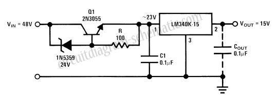
This circuit employs the LM340 voltage regulator to provide a stable 15V output. The LM340 is designed to operate within a specified input voltage range, as outlined in its data sheet. Exceeding the absolute maximum input voltage can lead to potential failure modes, primarily affecting the transistor Q1. When the output is shorted to ground, or if the output remains ungrounded, the transistor may experience excessive voltage across its collector-emitter junction, leading to its failure. The critical threshold for safe operation is approximately 4.0V below the input voltage.
To mitigate the risk of operating the LM340 outside its safe input voltage range, a zener diode can be implemented in series with the input voltage supply. This configuration effectively limits the input voltage to a safe level, thereby protecting the regulator and ensuring reliable operation. The zener diode should be selected based on the desired clamping voltage, which should be lower than the maximum input voltage rating specified for the LM340.
The schematic for this circuit should include the LM340 voltage regulator, the zener diode connected in series with the input, and the necessary bypass capacitors to stabilize the output voltage. It is also advisable to include a fuse or other protective components to safeguard against overcurrent conditions. The design should ensure that all components are rated appropriately for the expected voltage and current levels to maintain circuit integrity and reliability.This circuit can generate voltage 15V. In these circuit LM340 input voltage must remain within the limits specified in the data sheet. If the device is operated above the absolute maximum input voltage rating, two failure modes can occur. With the output shorted to ground, or, even with the output is not grounded, the transistor Q1 may fail becaus
e it is operated with the collector-emitter voltage of about 4. 0V below the input. If the supply is available only running at a higher voltage than the specified maximum, one of the simplest ways to protect the regulator is to connect the zener diode in series with input from the device to level shift the input voltage. Here is a schematic drawing: 🔗 External reference
Related Circuits
The diagram illustrates a series connection of cell diode capacitors, each rated for an increasing voltage of 300 V. This configuration generates a high DC voltage supply of 40 kV, which can be utilized for various experimental applications. With...
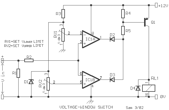
A voltage window switch is in practice the basic lower window limit of this circuit is roughly 3V and the upper limit is 9V. The window range can be extended by fitting a suitable range Part List R1-2=10Kohm D1=9V1/ 0.5W Zener...
This circuit diagram for a 12V inverter is simple to construct and utilizes inexpensive components that many electronics hobbyists may already possess. While it is feasible to create a more powerful circuit, the complexity arises from managing the significant...
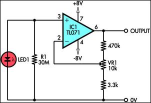
This circuit demonstrates the use of a standard LED as a light sensor by utilizing the photovoltaic voltage generated across the LED when it is exposed to light. LEDs are cost-effective alternatives to photodiodes and include a built-in filter...
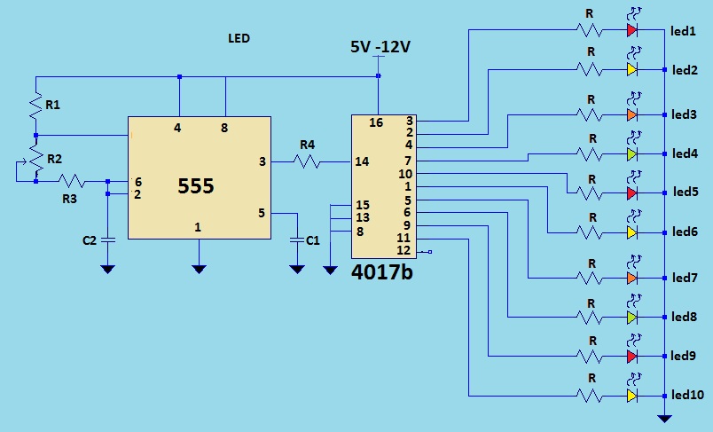
This is a LED sequencer circuit where 10 LEDs light up and turn off sequentially, creating a chasing effect. This simple circuit is suitable for designing lighting decorations on Christmas trees. It can also be used for lighting animations...
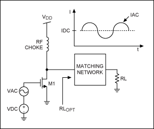
This application note provides a concise overview of power amplifier theory and presents simulation results that offer insights into the operation of the power amplifier across all of MAXIM's LFRF transmitters and transceivers. Power amplifiers are critical components in communication...
Warning: include(partials/cookie-banner.php): Failed to open stream: Permission denied in /var/www/html/nextgr/view-circuit.php on line 713
Warning: include(): Failed opening 'partials/cookie-banner.php' for inclusion (include_path='.:/usr/share/php') in /var/www/html/nextgr/view-circuit.php on line 713