
Low current touch switch
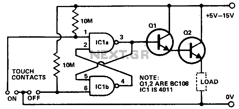
The circuit utilizes a Darlington pair configuration, which consists of two bipolar junction transistors (BJTs) connected in such a way that the current amplified by the first transistor (Q1) is further amplified by the second transistor (Q2). This configuration is advantageous for applications requiring high current gain, making it suitable for driving loads such as a transistor radio.
In this setup, the input signal is applied to pin 3, which is connected to the base of Q1. When a finger touches the on contacts, it effectively applies a high voltage to pin 3, causing Q1 to turn on. The base-emitter junction of Q1 becomes forward-biased, allowing current to flow from the collector to the emitter, which in turn activates Q2.
Q2 is selected based on the current requirements of the load circuit. It is essential that Q1 is a high-gain transistor to ensure that even a small input current can produce a sufficient output current to drive the load effectively. The output from Q2 can then be used to power devices that require higher currents, such as a small transistor radio.
The design must also consider the power ratings and thermal management of both transistors, especially Q2, which may dissipate significant power depending on the load. Proper biasing resistors and possibly a heat sink for Q2 may be necessary to ensure reliable operation under varying load conditions. Additionally, protective components such as diodes may be incorporated to prevent back EMF from inductive loads, ensuring the longevity and stability of the circuit.Touching the on contacts with a finger brings pin 3 high, turning on the Darlington pair and supplying power to the load (transistor radio etc) Ql must be a high gain transistor, and Q2 is chosen for the current required by the load circuit. 🔗 External reference
Related Circuits
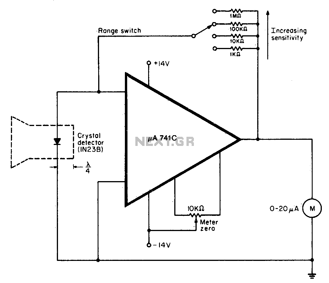
A waveguide directs energy onto a crystal detector during operation. The diode utilized is designed for X-band operation. The waveguide consists of a 1-inch piece of plastic tubing with flared ends. The plastic surface is treated with an electroless...
Self-switching power supply. One of the main features of the regulated power supply circuit being presented is that, although a fixed-voltage regulator LM7805 is used in the circuit, its. The self-switching power supply circuit utilizes the LM7805 voltage regulator to...
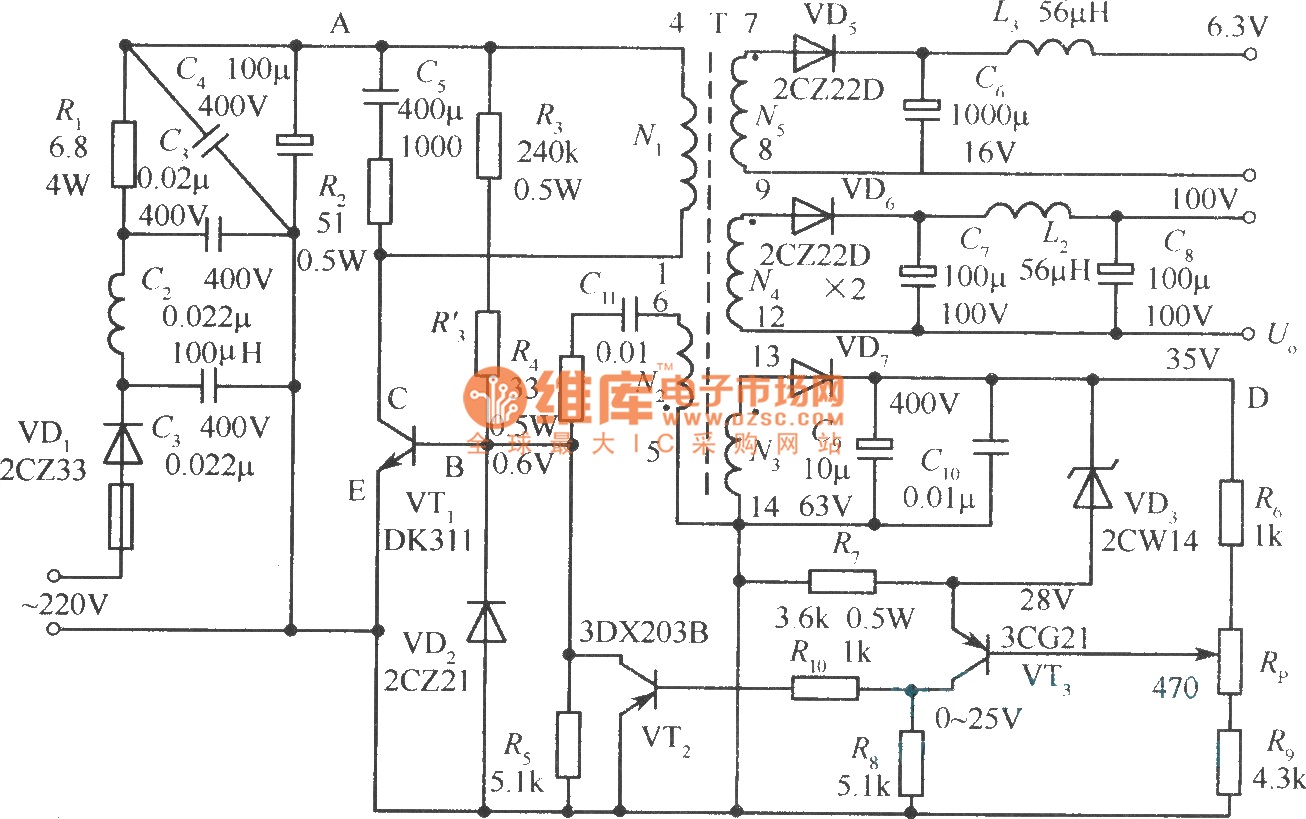
The diagram illustrates the output sampling winding of an isolated switching power supply. In the diagram, T represents a high-frequency transformer; N2 denotes the self-oscillation positive feedback winding; N3 is the error amplifier; VTS is the winding that provides...
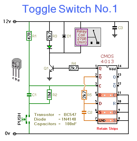
This circuit energizes and de-energizes a relay with the push of a button. Any momentary push-to-make switch can be utilized. Pressing the button once energizes the relay, while pressing it a second time de-energizes the relay. The circuit is...
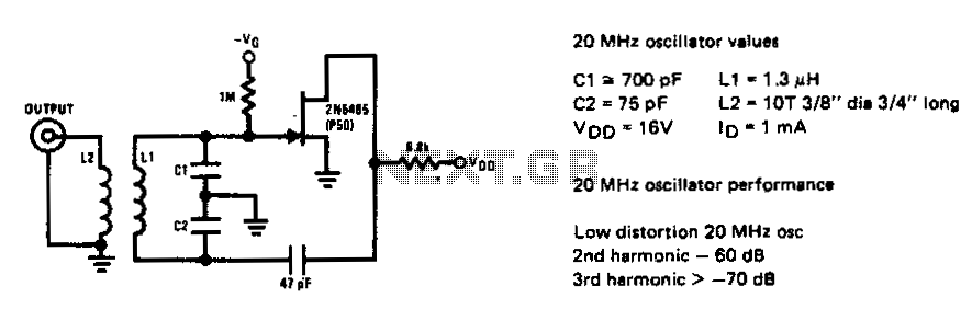
The 2N5485 JFET can oscillate in a circuit with very low harmonic distortion. This JFET local oscillator is ideal when low harmonic content is needed for an effective mixer circuit. The 2N5485 is a Junction Field Effect Transistor (JFET) that...
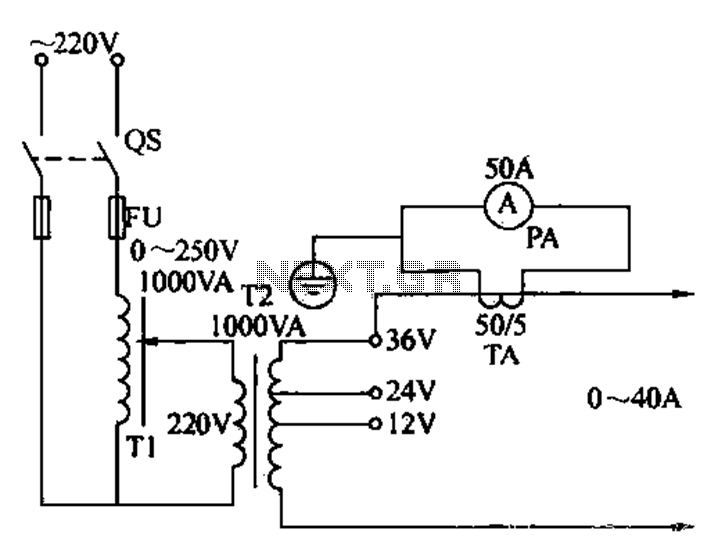
Electricians sometimes use overcurrent relays, thermal relays, and other devices to perform periodic overcurrent checks with a current generator. A secure running lights transformer, voltage regulator, and meter can be constructed using a small electric current generator. The homemade...
Warning: include(partials/cookie-banner.php): Failed to open stream: Permission denied in /var/www/html/nextgr/view-circuit.php on line 713
Warning: include(): Failed opening 'partials/cookie-banner.php' for inclusion (include_path='.:/usr/share/php') in /var/www/html/nextgr/view-circuit.php on line 713