
Low Distortion Crystal Oscillator
The low distortion crystal oscillator circuit is designed to produce a stable sine wave output with minimal phase noise and distortion, making it suitable for high-precision applications. At the core of the circuit is a quartz crystal, which serves as the frequency-determining element. The crystal's high Q-factor ensures that the oscillator operates at its fundamental frequency with excellent stability.
The circuit typically includes an amplifier stage, which boosts the signal generated by the crystal. This stage is often configured as a feedback loop to maintain oscillation. Commonly, a Colpitts or Hartley oscillator configuration is employed, where the feedback network is formed by capacitors and the crystal itself.
To further enhance the performance, additional components may be included, such as low-noise voltage regulators to provide a stable power supply, and filtering capacitors to eliminate high-frequency noise. Output buffering may also be implemented to drive loads without affecting the oscillator's performance.
The output frequency can be adjusted by selecting different crystals or by using variable capacitors in the feedback network. The circuit may also incorporate temperature compensation techniques to maintain frequency stability over varying environmental conditions.
This low distortion crystal oscillator circuit is widely used in telecommunications, audio applications, and precision measurement instruments, where signal integrity is paramount. Its ability to generate clean sine waves makes it an essential component in various electronic systems.This is a Low Distortion Crystal Oscillator circuit. This circuit generate a sinewave that has low phase noise and distortion. This circuit can be used to. 🔗 External reference
Related Circuits
Its most useful application is as a signal injector for radios and TVs. A square wave is the most suitable for testing the intermediate frequency (IF) strip as the signal will pass through the IF transformers without any attenuation,...
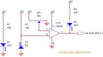
This circuit diagram illustrates a Line Follower / Line Tracker robot. The circuit is derived from tutorial documentation, which is available for download at the conclusion of this article. The line follower robot utilizes eight proximity sensor modules. Each...
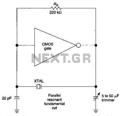
The CMOS amplifier is biased into the linear region by resistor RB. The pi-type crystal network (C1 and C2, and XTAL) provides the 180-degree phase shift at the resonant frequency, which causes the circuit to oscillate. The described circuit utilizes...

Without a heatsink, Triac Q1 can handle a load of up to a 400-watt lamp. The neon lamp does not trigger the gate until it begins conducting, resulting in the lamp turning on with medium brilliance. Subsequently, the lamp...
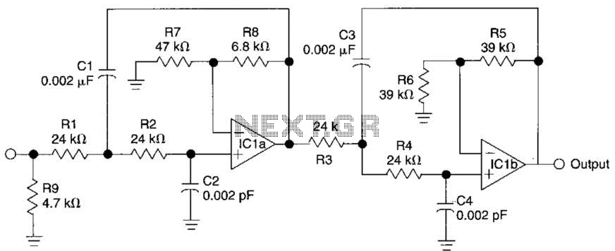
This circuit is a fourth-order low-pass filter designed for operation at kilohertz frequencies. The component values for resistors R1, R2, and capacitors C1, C2, as well as resistors R3, R4 and capacitors C3, C4 can be adjusted for functionality...
The hobby circuit described can be connected to a 3V battery to provide a warning when the battery is nearing its end of life. It will flash an LED when the battery voltage drops to approximately 2.4 volts. The...