
Microphone Circuit Test Oscillator

The circuit operates primarily with a dual op-amp, the 1458, which is well-suited for low-power applications. The three-stage phase shift oscillator utilizes resistors and capacitors to create the necessary phase shifts, facilitating stable oscillation. The design allows for a tunable frequency, which can be adjusted using a potentiometer, enhancing flexibility for applications requiring specific frequency outputs. The output stage is designed to buffer the oscillator's signal, ensuring that it can drive microphone inputs effectively without significant signal loss. The grounding of the metal enclosure is critical for minimizing noise and ensuring signal integrity, particularly in audio applications. Additionally, the choice of a linear potentiometer for output level control is essential, as it provides a more accurate representation of the signal level to the user. Overall, the simplicity of the design allows for easy assembly and integration into various audio testing setups, making it a practical choice for engineers and hobbyists alike.This circuit would be mounted in a small plastic or preferably metal box, with a 9V battery, level control, a male XLR connector (same as on a microphone) and a switch. Current drain is low, since the circuit only uses one dual op amp. There is no need for a high quality device, and a 1458 is all that is needed. The first stage is the oscillator i tself. This is a simple three stage phase shift oscillator - a circuit that is remarkably uncommon - which is to say I have never seen it used elsewhere. I designed it for another project a few years ago, and I dont understand why it is not in any op amp application notes.
Maybe I invented a new circuit. If you want to tune it, you can use a 50k pot instead of R1. I suggest that if tuned, set it to A-440 Hz. Frequency stability is not wonderful, and it changes by a few Hertz as the battery discharges, but this is unlikely to cause problems - it is a test oscillator, not a tuning standard. As shown, frequency will be about 430Hz, depending on the accuracy of the capacitors. The phase shift network (R1-C1, R2-C2 and R3-C3) serves two purposes. First (and for an oscillator, most importantly), it shifts the phase of the output signal so the feedback is positive, causing oscillation.
Secondly, since it is a three stage filter, it attenuates the signal and filters the output square wave so the signal at pin 2 is a reasonable sine wave. Distortion (if you really care) is about 3% or so - I didnt measure it this time, but I recall having done so before.
The second stage is the output buffer, and the signal is simply split to supply the two mic leads. The metal case should be connected to pin 1 (earth) on the XLR connector. The output level control must be a linear type, as the circuit loading will create a good approximation to a log pot. Maximum output into a typical microphone input will be about 100mV (unloaded oscillator output on mine was 140mV).
It is not much to it - the whole circuit can be built on a small piece of ferro board, and the battery, pot and XLR connector will take up far more room than the oscillator. There is no LED indicator for power, as this would draw more current than the circuit. To prevent accidentally turning it on, a slide switch is suggested. They are a pig to mount compared to a toggle switch, but are much less easily bumped. If you can get a pot with a switch, this would be even better, but these are now hard to get - especially as linear.
🔗 External reference
Related Circuits
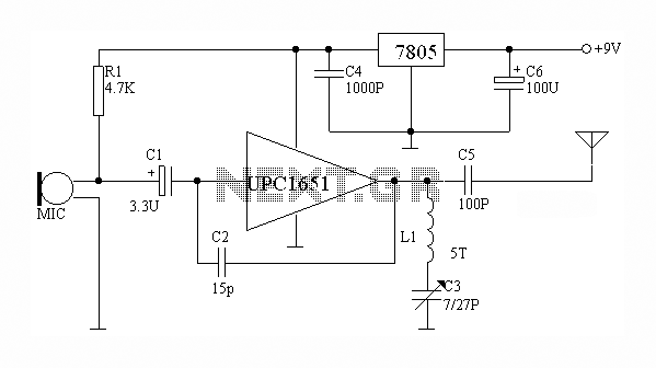
The circuit depicted utilizes the UPC1651 integrated circuit produced by NEC Corporation of Japan. It offers high gain and stability, ensuring optimal performance for microphones. The design incorporates an FM transmitter circuit. The system employs a flexible antenna measuring...
The concept for this crystal tester circuit originated from the necessity to evaluate a large quantity of oscillator crystals that were not in use within a hobby box. Testing each crystal individually without the proper equipment would have been...
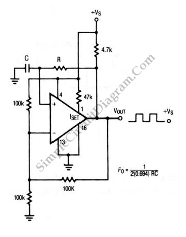
The circuit depicted in this schematic diagram is a square-wave oscillator circuit. The primary component of this oscillator circuit is the LP165/365 comparator. The square-wave oscillator circuit utilizes the LP165/365 comparator to generate a continuous square wave output. The...

This article outlines a lighting circuit designed to create a glowing firebox effect while providing constant illumination for classification lamps and an interior cab light. It includes comprehensive information necessary for constructing the circuit, such as a detailed schematic,...
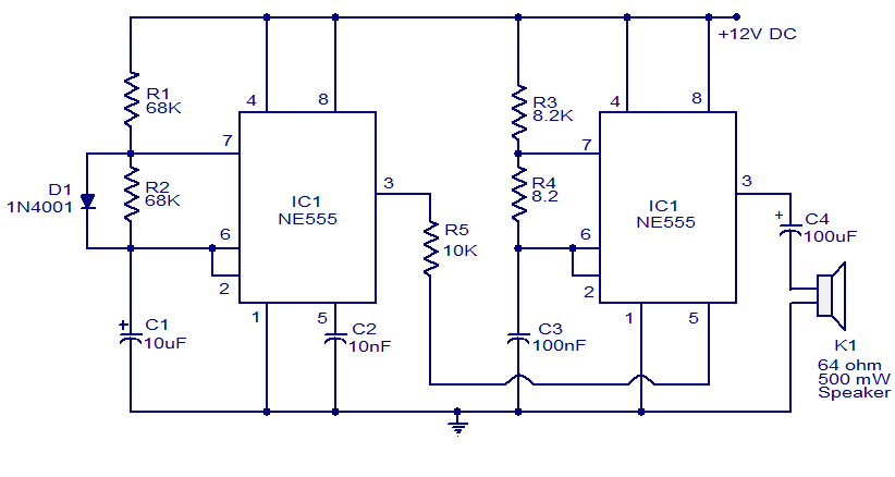
A variety of electronic circuits utilize the NE555 timer integrated circuit (IC). The circuit diagram presented illustrates a police siren based on two NE555 timer ICs, both configured as astable multivibrators. The circuit operates on a DC voltage supply...
This FM spy telephone circuit is connected in series with the phone line. When there is a signal on the wires, this transmitter will radiate airwaves through the wires. This FM spy telephone circuit operates by integrating with the existing...
Warning: include(partials/cookie-banner.php): Failed to open stream: Permission denied in /var/www/html/nextgr/view-circuit.php on line 713
Warning: include(): Failed opening 'partials/cookie-banner.php' for inclusion (include_path='.:/usr/share/php') in /var/www/html/nextgr/view-circuit.php on line 713