
Telephone Ringtone Generator Circuit
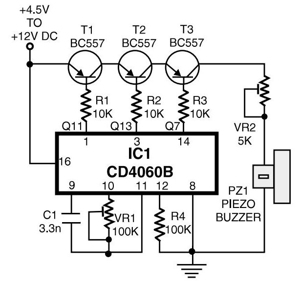
This circuit functions as a basic ringtone generator for home telephones, utilizing a minimal number of electronic components to achieve its purpose. The operation begins with a DC power supply, which can range from 4.5V to 12V, providing flexibility for various applications. The CD4060B integrated circuit (IC1) serves as the core of the design, generating three distinct frequency outputs through its internal oscillator. The frequency outputs are crucial for creating the characteristic ringing sound associated with telephones.
The preset variable resistor (VR1) allows for fine-tuning of the output frequency at pin 3 of IC1, which is set to 0.3125Hz. This low frequency is essential for the timing of the ringtone. The additional outputs at pin 1 and pin 14 provide 1.25Hz and 20Hz signals, respectively, which are utilized in controlling the operation of the transistors.
Transistors T1, T2, and T3 act as switches in the circuit, controlling the flow of current to the piezo buzzer. Resistors R1, R2, and R3 limit the base current to the transistors, ensuring they operate within safe limits. The piezo buzzer, designated as PZ1, is responsible for producing the audible ringtone, generating a frequency of approximately 1kHz when activated.
The operation of the piezo buzzer is modulated by transistor T3, which switches the buzzer on and off at a rate of 20Hz. This modulation creates a ringing effect, with pulses lasting 0.4 seconds followed by a 0.4-second silence, and then repeating this pattern with a two-second silence after every cycle. This timing emulates the ringing pattern of traditional telephones, making it suitable for home intercom systems.
Overall, this simple yet effective circuit design demonstrates how basic electronic components can be combined to create a functional and adjustable ringtone generator for home use.This is a simple home telephone ringtone generator circuit which is built with applying only several electronic components / parts. It generates simulated telephone ringtone and requires only DC supply with 4. 5V DC to 12V DC voltage. One may possibly use this circuit in ordinary intercom or phone-type intercom. The sound is pretty loud when this c ircuit is operated on +12V DC power supply. Even so, the volume of ring sound can be adjusted. CD4060B is chosen to produce three kinds of pulses. Preset VR1 is fine-tuned to get 0. 3125Hz pulses at pin 3 of IC1. At the same time, pulses obtainable from pin 1 will be of 1. 25 Hz and 20 Hz at pin 14. The three output pins of IC1 are connected to base terminals of transistors T1, T2, and T3 through resistors R1, R2, and R3, respectively. Working with a built-in oscillator-type piezobuzzer generates about 1kHz tone. In this particular circuit, the piezo-buzzer is turned on` and off` at 20 Hz for ring tone sound by transistor T3.
20Hz pulses are obtainable at the collector of transistor T3 for 0. 4-second duration. Just after a time interval of 0. 4 second, 20Hz pulses become again obtainable for another 0. 4-second duration. This is followed by two seconds of nosound interval. Thereafter the pulse pattern repeats by itself. Se trata de un sencillo generador de timbre de llamada para el telG©fono de casa que se construye con sG³lo unos pocos componentes electrG³nicos. Genera un tono de llamada telefG³nica simulada y sG³lo requiere de una alimentaciG³n de corriente continua de 4, 5 V a 12 V.
Se puede hacer uso de este circuito en sistemas de intercomunicaciG³n ordinarios que empleen aparatos de tipo telefG³nico. El sonido es bastante fuerte cuando este circuito es alimentado con +12 V. AG n asG, se puede ajustar el volumen del sonido de timbre. Se ha elegido el chip CD4060B (IC1) para producir tres tipos de impulsos. El trimmer VR1 se ajusta cuidadosamente para que IC1 genere impulsos de 0, 3125Hz en su patilla de salida 3.
Al mismo tiempo, los impulsos obtenidos en la patilla 1 serG n de 1, 25 Hz, y de 20 Hz en la patilla 14. Las tres patilla de salida de IC1 estG n conectadas a los terminales de base de los transistores T1, T2 y T3 a travG©s de las resistencias R1, R2 y R3 respectivamente.
El circuito funciona con un zumbador piezoelG©ctrico (piezobuzzer PZ1) con oscilador incorporado que genera un tono de 1 kHz aproximadamente. En este circuito en particular, el zumbador piezoelG©ctrico es activado y desactivado por el transistor T3 con una cadencia de 20 Hz, para proporcionar el sonido del timbre de llamada del telG©fono.
Los pulsos de 20 Hz estG n disponibles en el colector de T3 durante un intervalo de tiempo de 0, 4 segundos de duraciG³n, al cual sigue un intervalo de tiempo de 0, 4 segundos de silencio, y de nuevo otro intervalo de impulsos de 20 Hz de 0, 4 segundos de duraciG³n (periodos de 0, 4 segundos controlados por T2). Tras G©ste sigue un intervalo de silencio de 2 segundos (controlado por T1), tras el cual se vuelve a repetir cGclicamente este patrG³n de generaciG³n de impulsos.
Nota: Este circuito simula la cadencia de la llamada telefG³nica inglesa (. Ring. Ring . Ring. Ring . ), en EspaG±a la cadencia de la llamada telefG³nica es otra (1, 5 segundos de timbre y 3 segundos de silencio, de forma cGclica). 🔗 External reference
Related Circuits
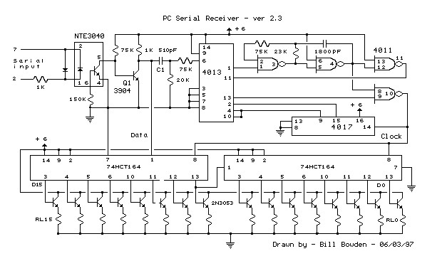
This circuit requires physical connections to be made to the computer's serial port (COM1 or COM2). It is generally considered difficult to cause harm to oneself or the computer through improper connections to this port; however, there is no...
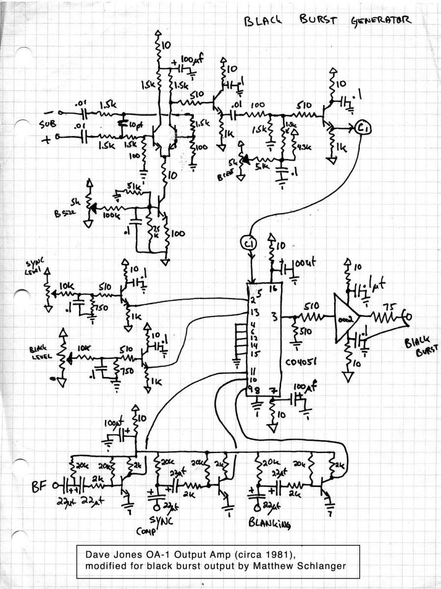
CMOS analog multiplexers are commonly utilized in electronic circuits for various applications. This document presents a modified circuit based on a design by Dave Jones, aimed at constructing a black burst generator. Sync signals are essential in video systems...
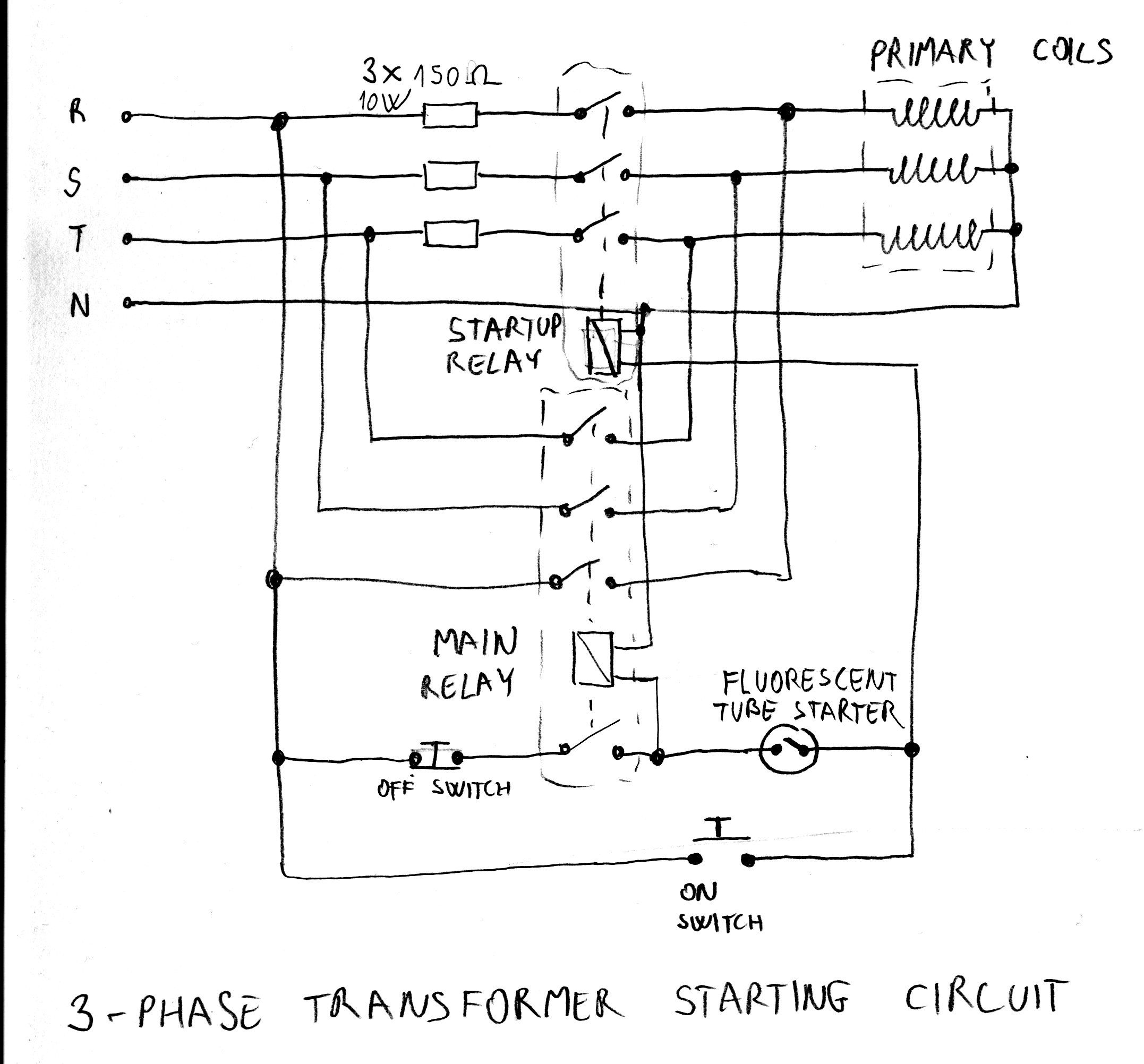
After acquiring a large 3-phase variable transformer (variac), there was an unexpected issue with it tripping circuit breakers at random when plugged in. Interestingly, the tripping occurred on different phases and seldom affected all three simultaneously. Resetting the breakers...
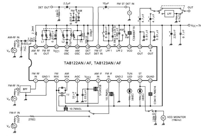
A simple low-power AM/FM radio receiver electronic project can be designed using the TA8122 integrated AM/FM receiver, manufactured by Toshiba Semiconductor. This radio receiver circuit is suitable for portable radio applications or other similar devices. The TA8122 radio receiver...
The current loop interface circuit diagram of the AD694 multi-functional sensor signal conditioner is utilized as a digital-to-analog converter (DAC). This current loop interface enables the conversion of digital values into voltage and subsequently into current signals. The circuit...
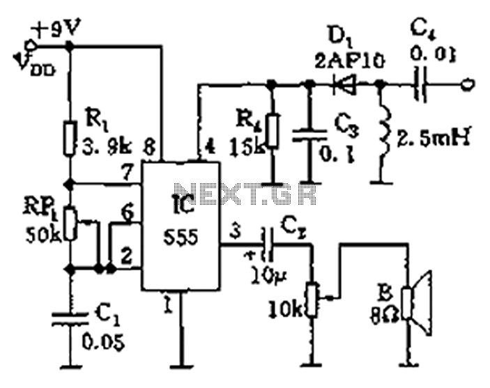
The circuit features a 555 timer integrated circuit along with components R1, RP1, C1, and others, which together form an audio oscillator. The frequency of the oscillator is determined by the formula f = 1.44 / ((R1 + 2...