
Simple Stand-Alone Voltage-to-Frequency Converter Using LM231/LM331

The LM231/331 series of voltage comparators can be effectively utilized to design a voltage-to-frequency converter. This configuration leverages the chip's ability to compare input voltage levels, generating a frequency output that is proportional to the input voltage. The fundamental operation involves applying a varying voltage to the non-inverting input of the comparator while the inverting input is connected to a reference voltage.
When the input voltage exceeds the reference voltage, the output of the LM231/331 transitions from low to high, producing a square wave signal. The frequency of this square wave is directly proportional to the amplitude of the input voltage. By integrating the output signal through a low-pass filter, the resultant frequency can be converted back into a voltage, enabling applications in analog-to-digital converters and frequency-to-voltage converters.
The circuit typically includes additional components such as resistors and capacitors to set the reference voltage and adjust the sensitivity of the converter. The choice of these passive components is crucial in determining the linearity and range of the converter. The output frequency can be measured using a frequency counter or processed further for digital applications, ensuring accurate representation of the input voltage over time.
This design approach is particularly useful in long-term monitoring applications where continuous voltage measurements are required, allowing for reliable data acquisition in various electronic systems.Using LM231/331 chip, we can build a low-cost voltage-to-frequency converter, ideal for analog-to-digital conversion, frequency-to-voltage conversion, long-term. 🔗 External reference
Related Circuits
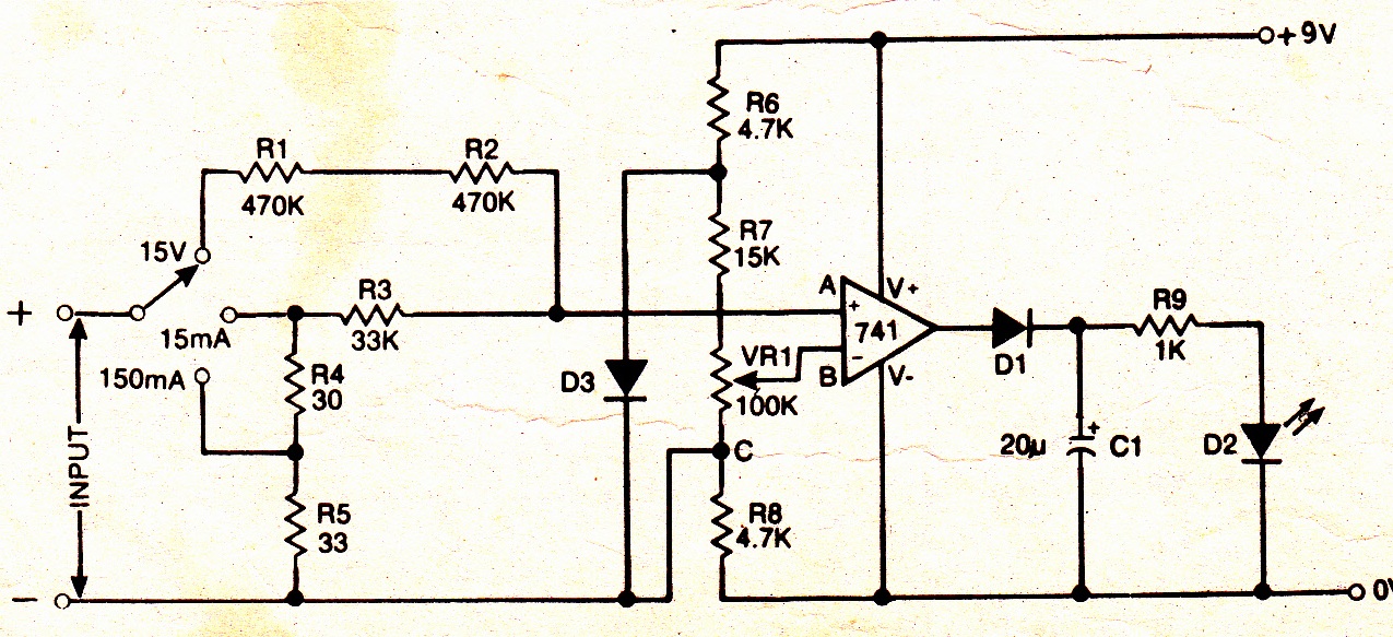
A simple electronic multimeter offers an affordable alternative for hobbyists deterred by the high cost of conventional multimeters. This device is designed to measure three ranges: (i) 0-15V, (ii) 0-15mA, and (iii) 0-150mA, with the possibility of extending the...

The following circuit illustrates a simple TV transmitter circuit diagram. This circuit is based on the LM1889 integrated circuit (IC). Features include quadrature chroma modulators and RF capabilities. The circuit utilizes the LM1889 IC, which is designed for television applications,...

The Door Buzzer circuit utilizes an IC 555 to generate a sound resembling an electric bell. When the switch S1 is pressed, a loud sound is produced. This circuit is designed to be simple and requires minimal components. It...
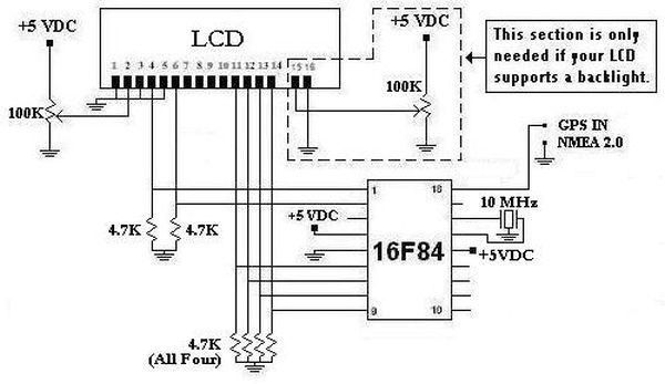
This project was initiated in late 2003 with the aim of learning PIC programming. The goal was to create a functional device that performed a specific task. The project involves the design and implementation of a microcontroller-based system utilizing a...
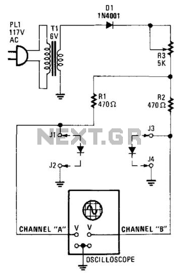
Suitable for matching diodes or examining the VI characteristics of two-terminal devices (such as diodes), this circuit is designed for laboratory use. Resistors R1 and R2 can be increased in value, and a higher voltage transformer can be utilized...
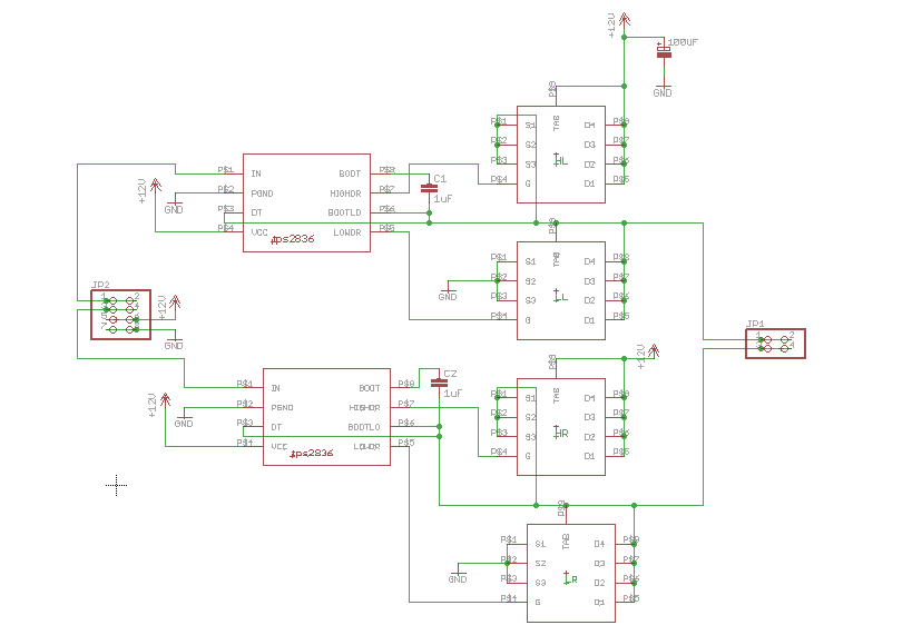
An H-bridge circuit was constructed using the TPS2836 and CSD16404 components. The schematic is provided below. However, the circuit is not functioning correctly, leading to several inquiries regarding potential design flaws. The power supply voltage (VDD-GND) is set to...