
Low noise microphone preamplifier circuit

The SSM2015 is a low-noise, low-distortion integrated circuit designed specifically for microphone preamplification. It features a differential input stage that provides excellent common-mode rejection, making it suitable for applications requiring high fidelity audio signal processing. The circuit typically includes resistors and capacitors that set the gain and frequency response to match the characteristics of the microphone being used.
In this schematic, the input stage connects directly to the microphone, converting the low-level audio signal into a more manageable voltage level. The gain of the SSM2015 can be adjusted by changing the feedback resistors, allowing for flexibility in handling different microphone types, such as dynamic, condenser, or electret microphones.
The output stage of the preamplifier is designed to drive subsequent audio processing stages or directly interface with analog-to-digital converters (ADCs). It is important to ensure proper power supply decoupling to minimize noise and maintain signal integrity throughout the circuit. Additionally, the layout of the PCB should be considered to reduce electromagnetic interference (EMI) and ensure optimal performance of the preamplifier.
Overall, the SSM2015 microphone preamplifier circuit is a robust solution for capturing high-quality audio signals, making it a popular choice in professional audio equipment and recording applications.The microphone preamplifier circuit design presented in this schematic use SSM2015 produced by Precision Monolithics Inc. (PMI) which offers a high amplifi. 🔗 External reference
Related Circuits
There is an advantage in using continuously active PWM signals. The main reason is that the asynchronous frequencies of the PWM core and microcore can sometimes result in a shortened PWM pulse. The servo recognizes this as a command...
There is no substitute for sheer power—low-efficiency speakers, outdoor sound systems, or perhaps the full dynamic range of a high-power amplifier. Whatever the requirement, this super power module should meet the needs. The amplifier can be divided into three...
When an individual touches the safety box or other protected metal objects, the sensor circuit generates a pulse to the alarm circuit. The positive edge of this pulse activates the semiconductor and thyristor flash GE, subsequently triggering the camera...
Using this low cost project, one can reproduce audio from a TV without disturbing anyone. It does not use any wire between the TV and headphones. Instead of a pair of wires, it uses invisible infrared light to transmit...
After being careful about every orientation of every transistor, a circuit board was designed around the LM387N, which was not the intended chip nor the one originally ordered (LM258, commonly referred to as LM358). During testing before adding larger...
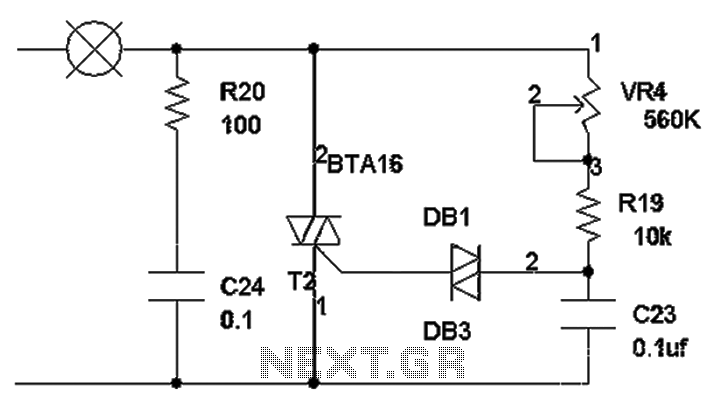
The TRIAC dimmer circuit diagram operates on the principle that a 220V lamp is controlled through the charging of capacitor C23 via resistors VR4 and R19. The charging time is influenced by the values of VR4 and R19, where...