
low power receiver serves multiple wireless standards
The dual-band receiver front end integrates a current-reuse amplifier and a switch-based mixer to achieve high performance while maintaining low power usage. The current-reuse amplifier is designed to maximize efficiency by reusing bias current, which minimizes power dissipation while providing sufficient gain for signal processing. This design is particularly beneficial in battery-powered applications where power efficiency is critical.
The switch-based mixer operates by utilizing electronic switches to selectively route signals from different frequency bands. This allows the receiver to process multiple frequency channels without the need for multiple separate mixers, thereby reducing component count and overall system complexity. The combination of these two technologies enables the receiver to achieve a wide dynamic range and improved linearity, resulting in better signal fidelity and reduced distortion.
In practical applications, this dual-band receiver front end can be employed in various communication systems, including wireless networks, satellite communications, and radio frequency identification (RFID) systems. The low power consumption characteristic is especially advantageous for portable devices, where battery life is a concern. Additionally, the compact design resulting from the integration of the amplifier and mixer contributes to a smaller overall footprint, making it suitable for space-constrained environments.
Overall, the synergy between the current-reuse amplifier and switch-based mixer in this dual-band receiver front end represents a significant advancement in receiver technology, optimizing performance while minimizing energy consumption.By combining a current-reuse amplifier and switch based mixer, a dual-band receiver front end offers excellent performance with extremely low power consumption.. 🔗 External reference
Related Circuits
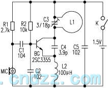
The loop antenna L1 is utilized for emission and also functions as the oscillation coil. The high-frequency current flowing through the antenna is synchronized in resonance with the oscillation frequency, ensuring optimal emission performance. Practical applications indicate that the...
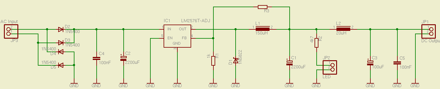
This is a simple and effective switched mode power supply (SMPS) designed to power an LCD monitor. It requires 20V at 2.3A, but the power supply unit (PSU) output voltage can be adjusted in the range of 1.2V to...
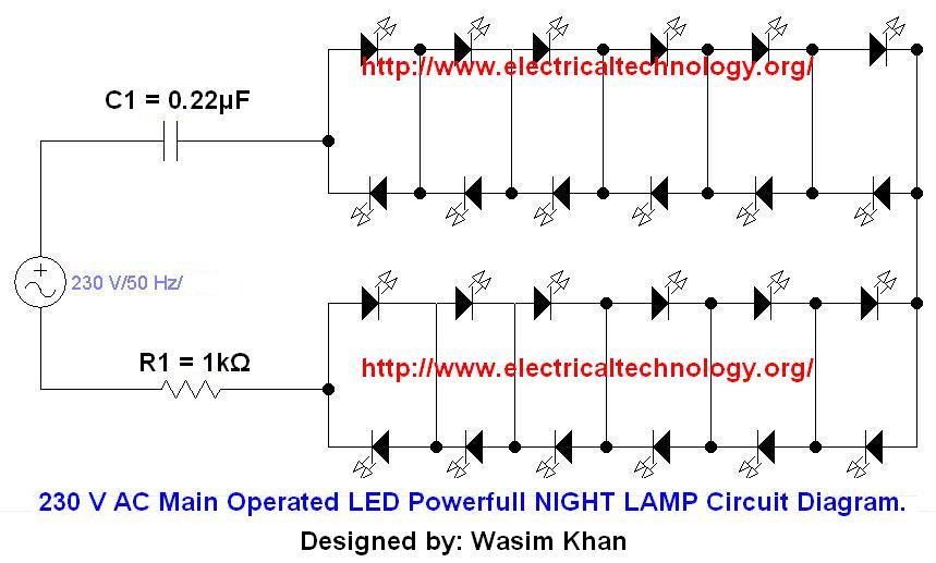
If you plan to use this circuit with a 110V 60Hz supply instead of a 230V 50Hz supply, or if you intend to modify this circuit, please refer to the section titled "Common Questions about this Circuit" found below...
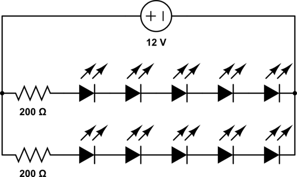
A 12V power supply is available, and there is a need to power LEDs with a forward voltage of 2V. It is questioned whether only six LEDs can be powered or if the cathode of one LED can be...
The circuit diagram for a multiple output digital camera power supply using the MAX1802 is illustrated below. The MAX1802 chip features two buck converters and three boost converters. It accepts an input voltage range of 2.5 to 11V and...
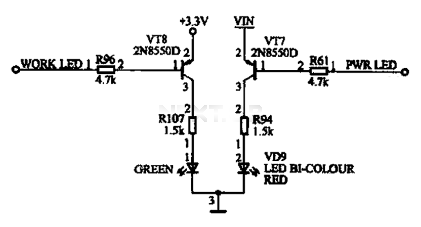
The ACER PM02 MP4 machine features a voltage status indicator circuit. When power is supplied, a red LED illuminates, indicating that the device is powered on. Upon entering operational mode, a green LED lights up. The voltage status indicator circuit...