
Low Voltage Adjustable Reference Supply
A low voltage reference circuit is designed to deliver a stable and precise voltage output that remains unaffected by variations in power supply and temperature. This type of circuit is crucial in applications where accurate voltage levels are required for biasing transistors, setting reference points for comparators, or providing a stable voltage source for analog-to-digital converters (ADCs).
The typical architecture of a low voltage reference circuit includes a voltage reference diode or bandgap reference, which ensures a stable output voltage. The circuit may also incorporate a series of resistors and capacitors to filter noise and stabilize the output. An adjustable feature can be achieved by including a variable resistor (potentiometer) in the feedback loop, allowing the user to fine-tune the output voltage according to specific requirements.
For implementation, the low voltage reference circuit can be powered by a stable supply voltage, and the output can be connected to various components that require a reference voltage. The design should take into consideration the load current and the desired output voltage range to ensure optimal performance.
In summary, a low voltage reference circuit is a critical component in many electronic systems, providing reliable voltage levels for biasing and reference purposes, with adjustable features to meet specific circuit needs.Low voltage reference is important to provide offset source or biasing, or just a reference for comparator, and its adjustable feature should suit this circuit.. 🔗 External reference
Related Circuits
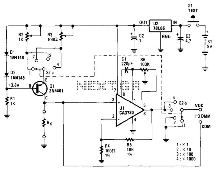
The circuit includes a 5-V regulator, a constant-current source (D1, D2, and Q1), and an operational amplifier (op amp) gain stage (U1). Power is supplied by a 9-V battery, which is regulated to +5 V DC by a three-terminal...
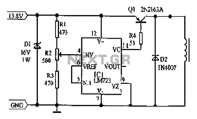
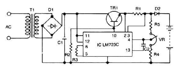
Cars are equipped with a circuit that includes an LM723 regulator, which can serve as a replacement for traditional automobile generator systems that utilize electromechanical charging regulators. This circuit offers superior performance compared to conventional systems. It ensures that...
The MAX1846 inverting circuit implements a switch-mode power supply that provides -15V at 0.5A output from a 4.5V to 12V input. This circuit incorporates additional components beyond the minimum implementation. C20 introduces a pole to compensate for the ESR-zero...
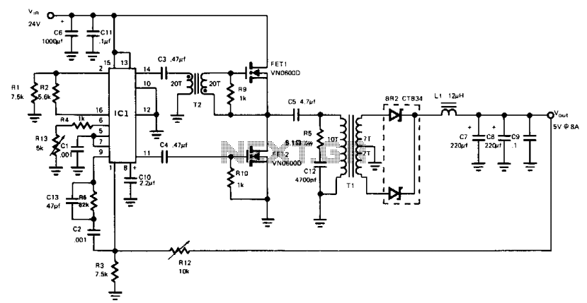
This buck-derived circuit delivers up to 8 A at 5 V DC while operating within an input voltage range of 24 to 32 V DC. The circuit utilizes two power MOSFETs that conduct alternately for equal durations. The switching...
The W7800 is a positive integrated voltage regulator, while the F007 consists of an operational amplifier used in a power supply tracking application circuit. Some configurations utilize both positive and negative power supplies, with a negative supply necessary to...
Constant Voltage Current Limited Charger power supply. Refer to the page for an explanation regarding the associated circuit diagram. The Constant Voltage Current Limited Charger power supply is designed to provide a stable output voltage while limiting the current to...