
Low-Ohms Adapter
The circuit is designed for precise measurement and testing of resistive components by utilizing a regulated power supply and a constant current source. The 5-V regulator ensures stable operation of the circuit, while the constant current source, facilitated by the diodes D1 and D2 and transistor Q1, maintains a consistent test current, which is critical for accurate resistance measurements.
The operational amplifier (U1) acts as a gain stage, amplifying the voltage drop across the resistor under test when higher ranges are selected. This amplification is essential for measuring low-resistance values accurately, as it increases the sensitivity of the measurement. The switch S2A allows the user to select between different test currents and ranges, providing versatility for testing various resistor values.
The multiturn trimmer potentiometers R2 and R3 allow for fine adjustment of the test current, ensuring that the circuit can accommodate a wide range of resistances without exceeding the limits of the DMM. The adjustment of R6 is crucial for calibrating the op amp, ensuring that any offset is corrected, and that the output accurately reflects the voltage across the resistor under test.
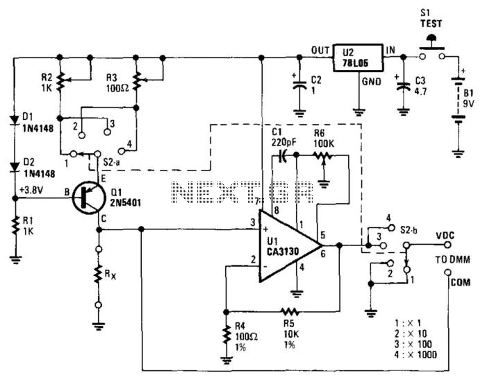
Overall, this circuit is an efficient and effective solution for testing and measuring resistances, providing both flexibility and precision in electronic applications. The circuit consists of a 5-V regulator, constant-current source Dl, D2, and Ql, and op amp gain stage Ul. Power is provid ed by a 9-V battery whose output is regulated to +5 Vdc by the 3-terminal regulator. The emitter of Ql is always 0.6 V below the +5-V line. Resistor R1 sets the current through both diodes Dl and D2 to 5 mA. The resulting 0.6 Vdc across one of the multiturn trimmer potentiometers (R2 and R3), as selected by switch section S2A, sets the current through Ql and the resistor-under-test. When R2 is selected, the test current is 1 mA; when R3 is selected, the test current is 10 mA. On the lower two ranges, 1 and 10, the voltage across resistance-under-test is applied directly to the DMM terminals.
On the upper two ranges, op amp gain stage Ul is switched into the circuit and the DMM measures the voltage between op amp output pin 6 and the test resistor. When switch S2 is in position 3 (x 100) the current set by the constant-current source is 1 mA; the multiplying factor is 100.
When S2 is in position 4, 1000, the current is 10 mA and the multiplying factor is 100 10 = 1000. Multiturn trimmer-potentiometer R6 adjusts the offset of the op amp so that, with no voltage across the resistor-under-test (i.e., with the measurement terminals short-circuited), the output is zero. 🔗 External reference
Related Circuits
This circuit provides a short circuit protected power supply from PC 12V supply voltage. This is particularly handy when working with PC interfacing projects. More: Fig-1 shows the circuit diagram of the complete power supply. The necessary 12V supply...
The device shows a voltage of 24V at no load on pins +4, 5 and -7, 8. This configuration is referred to as a passive power injector. When a current draw of 1A was attempted from the device, it...
This design modifies a high voltage flash for use with a low voltage camera by employing an optocoupler to provide electronic isolation between the camera's contacts and the high voltage. The flash can be triggered using the 6-volt supply...
Diode D1 and resistor R1 provide VDD isolation during the programming of 24-pin devices. Jumper J3 must be shorted for 24-pin devices and left open for programming 28-pin devices. The following EEPROMs are pin compatible with their EPROM versions. In...
This project is currently under construction and has not been validated for functionality. A signal generator, resistor, and oscilloscope were utilized to measure the value of an inductor for a battery charger project. In the search for an affordable...
There are monitors that feature only three BNC inputs and utilize composite synchronization (sync on green). This circuit has been specifically designed for such monitors. The design maintains simplicity while delivering reasonable performance. The operational principle is straightforward. The...
Warning: include(partials/cookie-banner.php): Failed to open stream: Permission denied in /var/www/html/nextgr/view-circuit.php on line 713
Warning: include(): Failed opening 'partials/cookie-banner.php' for inclusion (include_path='.:/usr/share/php') in /var/www/html/nextgr/view-circuit.php on line 713