
Magnetic Gun
The circuit employs a 555 timer (IC1) configured in astable mode, generating a series of square wave pulses approximately every 10 milliseconds. This output serves as a clock signal for the decade counter (IC2), which is a 4017 or similar IC capable of counting up to ten. The reset pin of IC2 is held low through resistor R3, allowing the counter to operate only when the "Fire" button is pressed, which brings pin 15 low. This action initiates the counting sequence, allowing the outputs Q1 to Q7 to activate in succession.
Each output from IC2 is connected to a power transistor (TR1 to TR4), which acts as a switch to control the flow of current to the electromagnets (L1 to L4). The rapid sequencing of these outputs energizes the electromagnets in a controlled manner, creating a magnetic field that propels the slug. The design allows for precise timing and control of the electromagnets, which is crucial for achieving the desired projectile motion.
The electromagnets are constructed on a 25 cm long, 3 mm diameter copper tube, commonly available in hobby shops. Each electromagnet consists of a core made from the copper tube, with two tin stops positioned at either end. Approximately 500 turns of 30 SWG (standard wire gauge) enamelled copper wire are wound between these stops, forming the coil necessary for generating the magnetic field when current is applied. This configuration is optimized for efficiency and performance, ensuring that the system can achieve the specified heights and distances for the projectile.Picured in Figure 1 is a miniature magnetic gun. When optimally tuned, it will propel a small slug about 1.5 metres high, or 2.5 metres horizontally. IC1 is a 555 timer in astable mode, sending approx. 10 ms pulses to decade counter IC2. IC2 is continually reset through R3, until pin 15 is taken low through the "Fire" button. IC2 then sequences through outputs Q1 to Q7, to feed power transistors TR1 to TR4, which fire electromagnets L1 to L4 in rapid sequence. The electromagnets are wound on a 25 cm long, 3 mm dia. copper tube (available at hobby shops). Two "stops" may be cut from tin for each electromagnet, and 500 turns of approx. 30 swg. enamelled copper wire wound between them. The electromagnets 🔗 External reference
Related Circuits
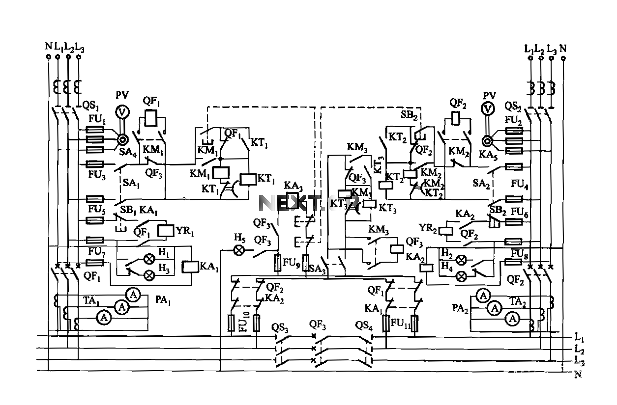
Dual power is provided for each complex, as the load is supplied through a two-way power system. In the event of a power outage, the contact switches transition from a closed position, allowing the power supply circuit to bear...
This device generates high-voltage pulses that disrupt muscles and the nervous system, causing mental confusion in anyone who comes into contact with it. It can be utilized against aggressive animals or attackers; however, it is important to note that...

Electromagnetic brake motors consist of a motor and an electromagnetic brake, forming a standard assembly. The circuit diagram is provided. In this configuration, FR represents the forward run and stop command terminal, while the intermediate relay KA is employed...

This amplifier is designed to be integrated with preamplifiers that lack a phono input. A phono input is essential for standard record players equipped with dynamic pick-ups, which remain widely used. The amplifier not only elevates the output of...

The Tupperware Turret circuit is designed to be straightforward while ensuring full functionality. The primary components in the schematic include the PIC 18F4520 microcontroller, servo motors, an infrared (IR) receiver, and a TIP120 transistor. This project is powered by...
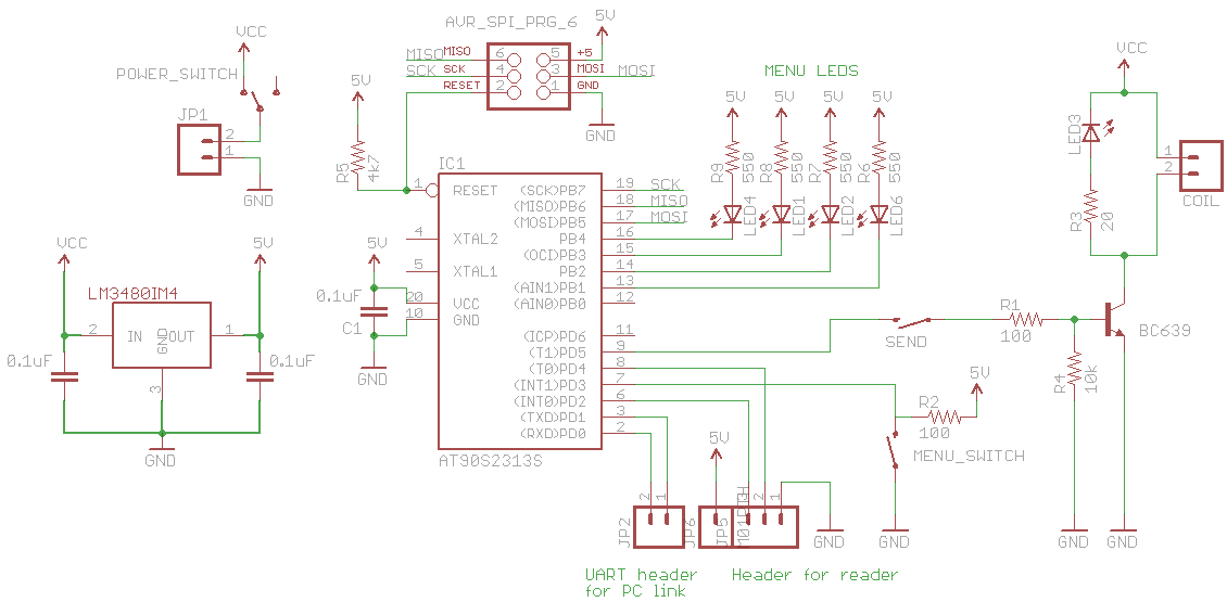
Approximately one year ago, a magnetic swipe card reader was included in a larger order from Digikey. At the time, there were no specific plans for its use; the primary motivation was curiosity about swipe cards and the types...