
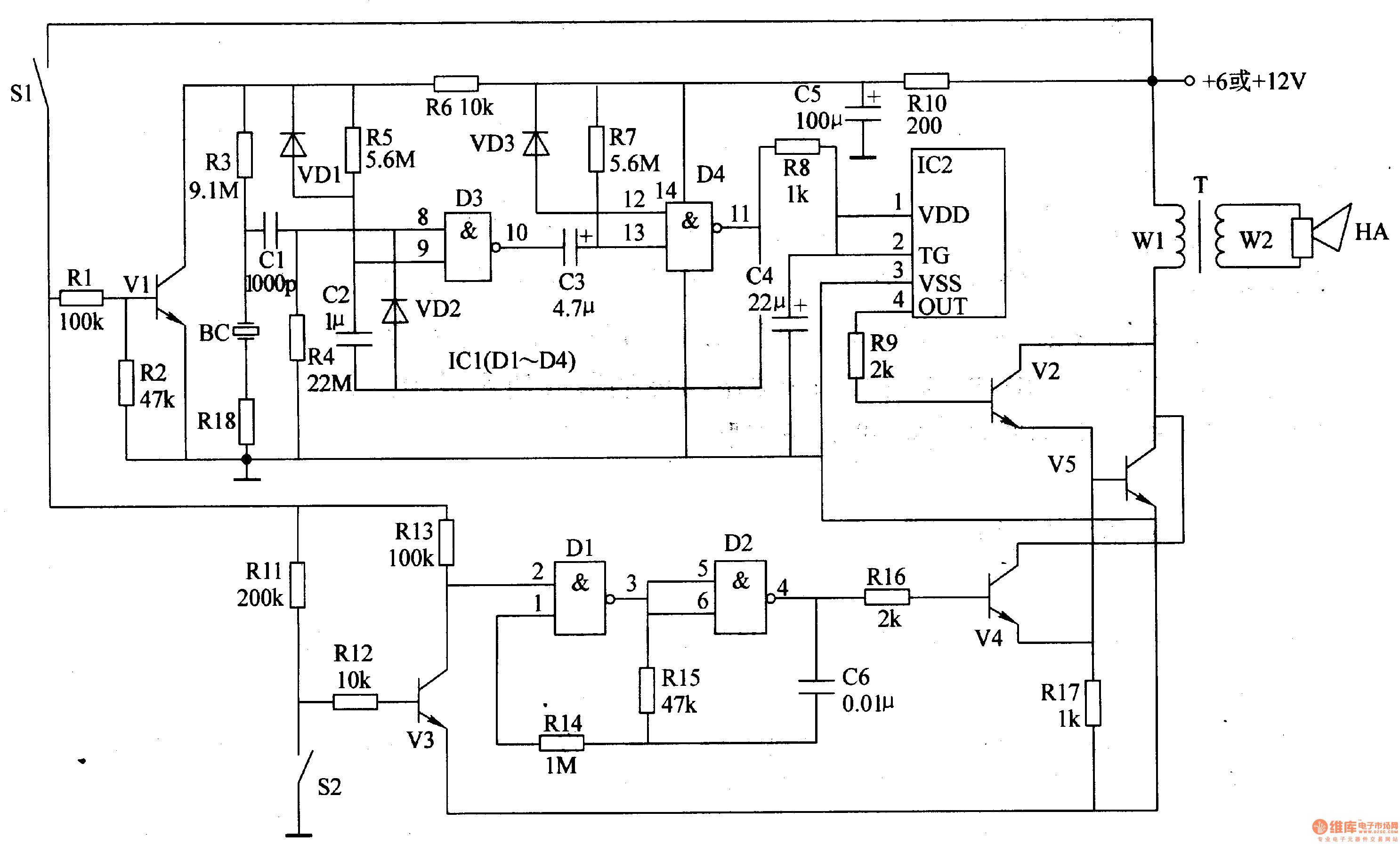
Mains Failure Alarm
The circuit functions by monitoring the presence of mains voltage. It typically utilizes a relay or a microcontroller to detect when the power supply is lost. Upon sensing the interruption, the circuit activates an audible alarm, which can be a buzzer or a speaker, alerting the user to the power failure.
The key components of this circuit may include:
1. **Power Supply Unit**: This converts the mains voltage to a lower voltage suitable for the circuit operation.
2. **Voltage Sensing Circuit**: This could be implemented using a transformer or an opto-isolator to safely detect the presence of mains voltage.
3. **Control Circuit**: A relay or microcontroller processes the signal from the voltage sensing circuit. If the mains voltage is interrupted, the control circuit triggers the alarm.
4. **Alarm Output**: The output stage of the circuit consists of an audible alarm, which can be a piezo buzzer or a speaker, designed to generate sufficient sound levels to alert users effectively.
Additional features may include an LED indicator to visually signal the power interruption, and a reset mechanism to silence the alarm once the power is restored. The circuit can also be designed with adjustable sensitivity to prevent false alarms due to brief power fluctuations.
Overall, this circuit serves as a crucial safety mechanism for individuals and businesses that rely on uninterrupted power supply, ensuring immediate notification of power outages.This circuit was designed to produce an audible alarm when the mains power is interrupted. Such an alarm is essential for anyone whose livelihood depends.. 🔗 External reference
Related Circuits

This is a complete alarm system with five independent zones suitable for a small office or home environment. It utilizes three CM integrated circuits and features a timed entry/exit zone, four immediate zones, and a panic button. There are...

The B8422 Nixie tubes are intended for use in an alarm clock on a bedside table. The collection of homemade clocks in the house has expanded, with the bedroom remaining unaffected by this clock-making enthusiasm. The B8422 Nixie tubes,...

This light alarm schematic circuit is designed using common electronic components, as illustrated in the circuit diagram below. The light alarm circuit will activate an alarm as soon as the drawer is opened and light falls on the Darlington...
This schematic is simple and easy to construct. The integrated circuit (IC) generates all the sound effects, with the output at Pin 3 being amplified by a transistor. A 64-ohm loudspeaker can be used instead of the 56-ohm resistor...
The motorcycle anti-theft alarm circuit consists of several components, including the anti-theft detection circuit, the control circuit, the sound generator, the audio oscillator, and the power amplifier output circuit, as illustrated in figure 7-91. The anti-theft detection circuit is...
This water level alarm circuit can be utilized as a water level indicator to monitor the desired water level in various applications, such as tanks, swimming pools, or any location where water is stored. The circuit is constructed using...