
Mains Failure Indicator

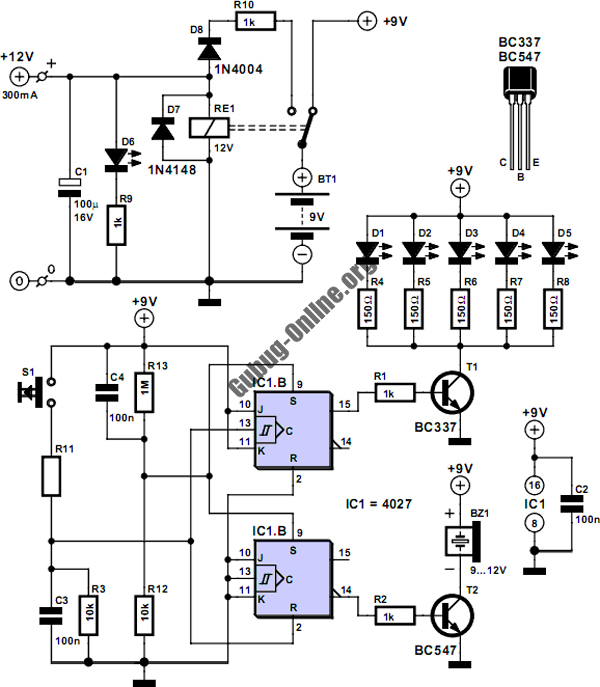
The circuit described operates as a mains failure detection system utilizing an optocoupler for isolation and a piezoelectric buzzer for audible alerts. The optocoupler's transistor serves as a switch that is activated when mains voltage is present, ensuring that the SCR remains off and the buzzer inactive. The SCR, once triggered, maintains its conducting state even when the mains voltage drops, due to its latching behavior. In this scenario, the potential difference created across the buzzer and diode D5 becomes sufficient to activate both components, providing a clear indication of power loss.
The reset mechanism is critical for restoring the circuit to its normal operational state. When the reset button is pressed, the current path through the SCR is interrupted, allowing the thyristor to stop conducting. This action effectively grounds the buzzer, silencing it until the next occurrence of mains failure. The design's reliance on a 9-V battery ensures portability and ease of use, while the low quiescent current minimizes battery drain.
Careful consideration must be given to the enclosure's insulation to prevent accidental short circuits, particularly in the region surrounding the optocoupler and associated components. The risk of damage to capacitor C2 is a significant concern; thus, it is imperative to maintain the integrity of the circuit connections. The recommendation to include a resistor across capacitor C1 serves as a safety measure, discharging the capacitor when the mains supply is disconnected, thereby preventing potential hazards during maintenance or service. Overall, this design effectively combines simplicity and functionality to provide reliable mains failure detection and alerting capabilities. When the mains voltage is present at the input terminals, the transistor in the optocoupler is on, T1 is off, and s ilicon-controlled rectifier Thl is in the conducting state. Because both terminals of the piezoelectric buzzer are then at the same potential, the buzzer is inactive. If the mains voltage drops out, transistor T1 conducts and causes one of the terminals of the buzzer to be connected to earth; the thyristor remains in the conducting state.
In this situation, a large enough potential difference is across both the buzzer and D5 to cause these elements to indicate the mains failure—both audibly and visibly. When the mains is restored, the circuit returns to its original state. A touch on the reset button then interrupts the current through the SCR so that the thyristor goes into the blocking state, and the other terminal of the buzzer is connected to ground.
The unit is powered by a 9-V battery and draws a quiescent current of 1.7-2.5 mA. It is important for the enclosure to be well-insulated. If by accident the circuit to the optocoupler and R2 is broken, electrolytic capacitor C2 might be damaged because it will be charged well above its 25-V rating. Secondly, where a plug is used for the mains connection, it is advisable to solder a 1- resistor across CI so that this capacitor does not retain its charge after the plug is removed from the mains socket.
🔗 External reference
Related Circuits

As the only electronics engineer in the family and circle of friends, it is sometimes challenging to decline requests for assistance. Recently, a friendly elderly lady in a retirement home sought help regarding her lighting situation. In her room,...
This circuit is designed to control the mains pulse. The pulser's purpose is to switch the mains voltage on and off at intervals ranging from just under one second to a maximum of ten minutes. This functionality is beneficial...

A neon lamp can easily be added to the phone line to act as a ring indicator. It is perfect for times when you cannot hear the phone. The integration of a neon lamp as a ring indicator in a...

A state-of-charge indication of a sloping-voltage discharge can be utilized as a state-of-charge indicator. A typical voltage comparator circuit that provides a visual indication of the state of charge is presented. Components identified are for a 4-cell input voltage...
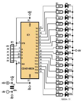
The indicator described here is specifically designed for adjusting the dynamic limiter outlined elsewhere in this edition and checking if the maximum level of the reference voltage (P1) requires modification. A 4-to-16 decoder integrated circuit (IC) of type 4514...

In the event of a sudden power failure in an elevator, it is crucial for the duty officer in the distribution room to be alerted promptly to prevent panic among passengers trapped inside. The following describes a sound alarm...
Warning: include(partials/cookie-banner.php): Failed to open stream: Permission denied in /var/www/html/nextgr/view-circuit.php on line 713
Warning: include(): Failed opening 'partials/cookie-banner.php' for inclusion (include_path='.:/usr/share/php') in /var/www/html/nextgr/view-circuit.php on line 713