
power Voltage supply clipping to <=3.3V
The circuit described requires a power supply sourced from a Lithium-Ion (Li-Ion) cell, which operates within a voltage range of 2.7V to 4.2V. The design aims to avoid the complexity associated with buck or boost converters, which are typically used for stepping down or stepping up voltages. Instead, a simpler voltage regulation method is preferred.
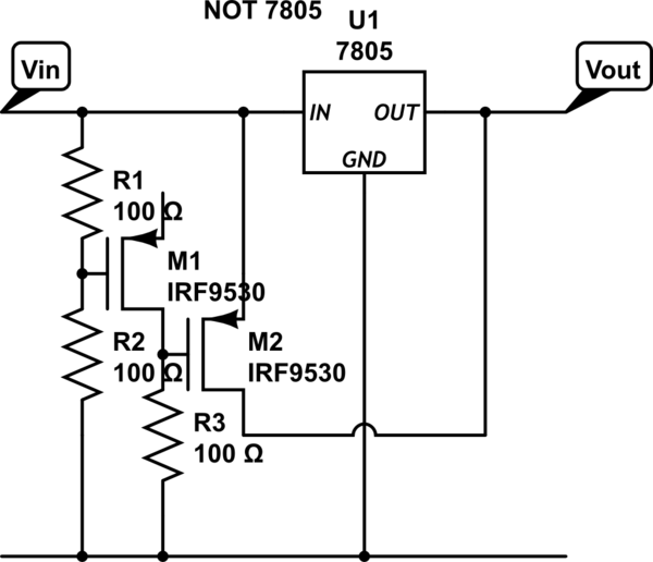
For input voltages above 3.3V, the circuit should output a stable 3.3V. This can be accomplished using a linear voltage regulator, which provides a straightforward solution without the need for complex circuitry. A common choice for such an application is the LM1117-3.3, which can handle input voltages up to 15V and provides a fixed output of 3.3V with a maximum load current of 800mA. The LM1117 operates efficiently within the specified input voltage range and has a dropout voltage of approximately 1.2V, which is suitable given the maximum input voltage of 4.2V from the Li-Ion cell.
For input voltages at or below 3.3V, the circuit should simply pass the input voltage through to the output without any regulation. This can be achieved by configuring the output stage of the circuit to allow direct connection of the input voltage to the output when the input voltage is less than or equal to 3.3V. A suitable component for this purpose could be a P-channel MOSFET, which can be used as a high-side switch. The gate of the MOSFET can be controlled by a simple voltage comparator that senses when the input voltage drops below 3.3V, allowing the circuit to switch between the linear regulator output and the direct input voltage seamlessly.
In summary, the proposed circuit design utilizes a linear voltage regulator for conditions where the input voltage exceeds 3.3V, while allowing direct passthrough of the input voltage when it is less than or equal to 3.3V, thus achieving the desired voltage regulation without the added complexity of a buck or boost converter.Supply it with a Li-Ion cell, which has 2. 7-4. 2V. I don`t really want/need the complexity of a buck/boost converter. I know I could just regulate it down to anything below 2. 5V, but it still would be great if my circuit would get 3. 3V for Input-Voltages above 3. 3V and the input voltage for anything <=3. 3V. 🔗 External reference
Related Circuits
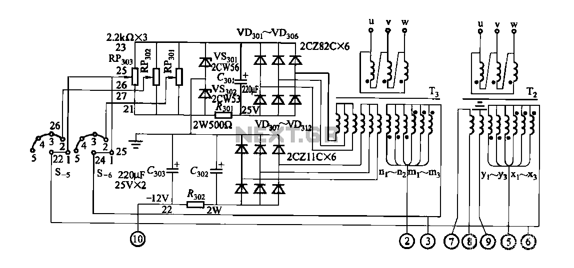
FGDF-3 is a three-phase low-temperature iron plating power supply circuit, while the KGDF-3 is a single-phase low-temperature iron plating power supply device that encompasses all the characteristics of the power supply unit. This design allows for an even distribution...
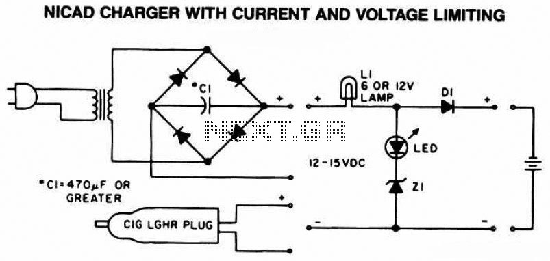
The following diagram is the schematic of a Ni-CAD battery charger circuit, which includes current and voltage limiting features to extend the battery's lifespan. The lamp L1 will illuminate brightly, and the LED will be off when the battery...
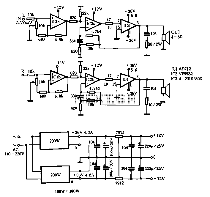
The T amplifier circuit schematic section is illustrated in Figure 3-51. It utilizes the Japan Sanyo STK6303 Pina, which is a high-power thick film integrated circuit. The maximum power supply voltage is 36V, and the output current can reach...
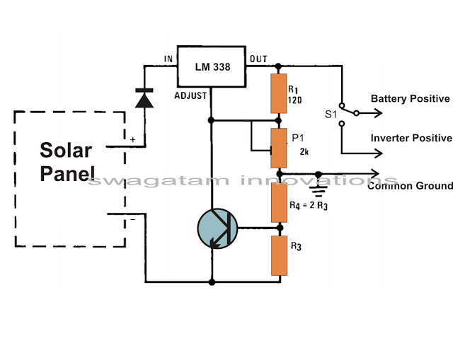
Solar panels are well-known devices that convert solar energy or sunlight into electricity. A solar panel consists of discrete sections of individual photovoltaic cells, each capable of generating a small amount of electrical power, typically between 1.5 to 3...
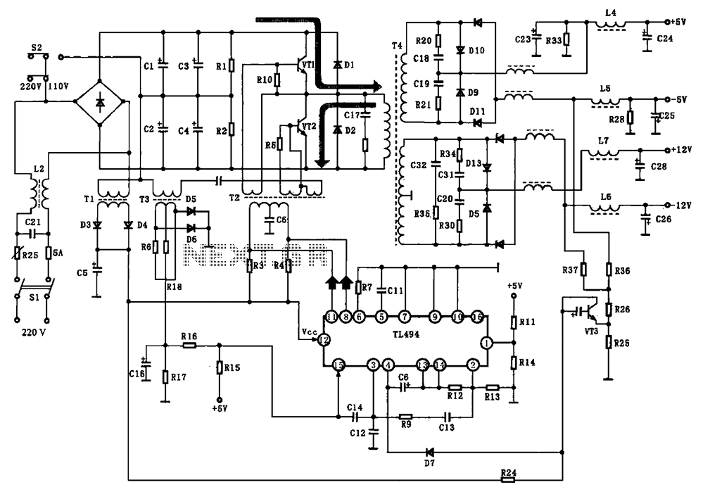
The BE-150 mainframe computer features a switching power supply circuit. The circuit utilizes the oscillation control IC TIA94. A 22V voltage is supplied through the power switch S1, fuse, filter capacitor C21, L2, and a mutual inductance filter, which...
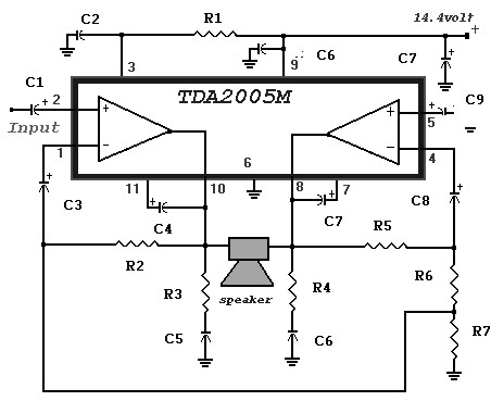
A 20 Watt car power amplifier circuit diagram based on the TDA 2005. The TDA 2005 IC is specifically designed for power boosting applications in car audio systems. This IC includes protection against short circuits and overheating. The circuit...