
Automatic tracking solar controller circuit
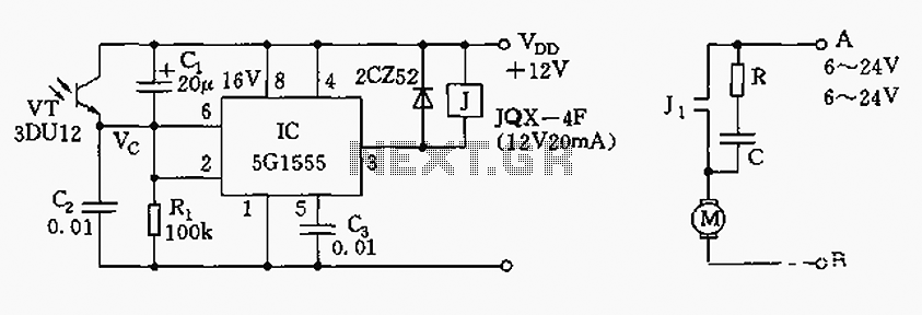
The circuit operates based on the principles of light detection and feedback control. The NE555 timer is configured in a monostable mode, where it monitors the voltage levels at its input pins. The photodiodes 3DU12 serve as light sensors, adjusting their resistance in response to varying light conditions. This change in resistance directly influences the voltage at pin 6 of the NE555 timer, which is critical for determining the operational state of the circuit.
Resistor R1 and capacitor C1 play a vital role in setting the time constants for the charging and discharging cycles, thereby controlling the responsiveness of the motor to light changes. The relay J acts as a switch, allowing the circuit to manage the power supplied to motor M. The motor is designed to rotate slowly, providing precise control over its position, which is essential for effective sun tracking.
The design ensures that the motor only operates when sufficient light is detected, thus conserving energy and preventing unnecessary wear. The feedback mechanism allows the motor to adjust its position in real-time, responding to changes in light intensity detected by the photodiodes. This results in an efficient and reliable sun-tracking system that can be used in various applications, including solar panels and other solar energy devices.As illustrated, the control circuit by the NE555 and phototransistor, R1, C1, C2 and so on. Photodiodes 3DU12 when sunlight to photodiodes, due to its resistance becomes smaller, so that the voltage of the circuit 555 is greater than 6 feet, 6 feet threshold level 2 / 3VDD, the circuit is in the reset state, 3-pin output is low level, the relay J pull, Figure (B), J1 contact connected to the motor M starts to drive slowly rotating gear. Go to a certain angle, photodiode light because it weakened resistance gradually increased, so that the charging time due to C1 potential drop of 2 feet, the light level is below the pin 1 / 3VDD, the flip circuit 555, 3-pin output It showed a high level "1" relay J release, the motor stopped due to power failure, when the sun again illuminated photodiodes, and start the motor, branched sun tracking.
Related Circuits
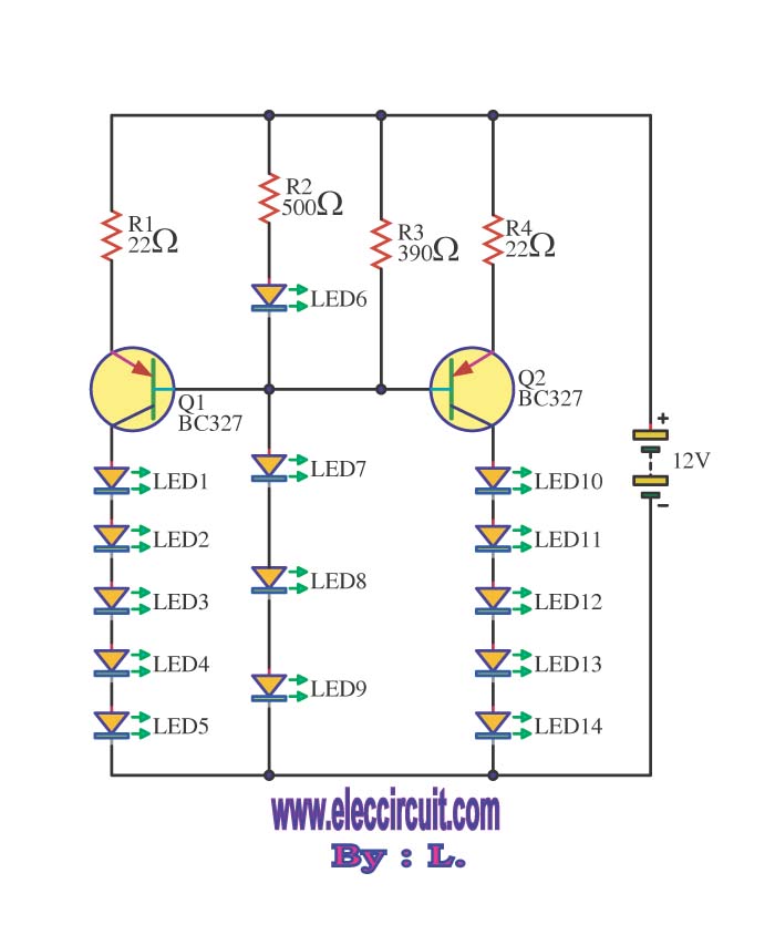
This circuit enables the brake light to flash. The default behavior occurs when power is supplied to the circuit or when the brake is engaged. The timer IC (IC2) drives current to the transistor (Q2), producing an oscillating output...
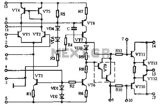
A preferred STK4040xl Fi amplifier circuit exhibits excellent electrical parameters: under specific conditions, the output voltage (Uc) is 43V with a load resistance (RL) of 8 ohms. The circuit is designed to deliver a rated output power of at...

This circuit produces a soft turn-on for halogen lamp filaments upon powering up. The MOSFET used is a BUZ10, which has a resistance of 0.2 ohms. Resistors R1, R2, and capacitor C1 set the turn-on rate, while diode D1...
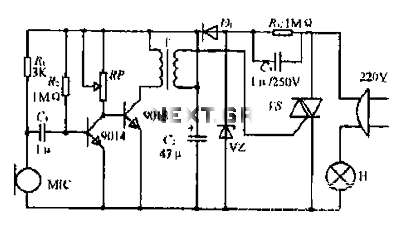
22W by Ct and R, RC Buck, rectified by n. c, filtering. vz 3V DC regulated output power, before U, V2 and MIC power supply. When the audio signal reaches the beam, the microphone MI converts acoustic energy into...

Here is a design for a temporary lamp circuit that is very helpful in emergency situations or in any application where there is limited time to turn off the lamp. Simply press the push button to perform a quick...
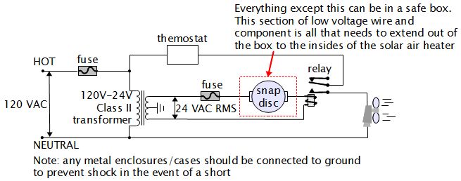
For various experiments, such as solar air heaters, an automatic fan activation and deactivation system is required. A straightforward solution is to use a bimetal snap disc thermal sensor. This sensor functions as a switch that closes when a...
Warning: include(partials/cookie-banner.php): Failed to open stream: Permission denied in /var/www/html/nextgr/view-circuit.php on line 713
Warning: include(): Failed opening 'partials/cookie-banner.php' for inclusion (include_path='.:/usr/share/php') in /var/www/html/nextgr/view-circuit.php on line 713