
make this solar powered fence charger
The solar electric fence charger circuit is designed to efficiently convert solar energy into a high-voltage output suitable for energizing electric fences. The primary components of this system include a solar panel, a charge controller, a 555 timer IC configured as an oscillator, an ignition coil, and a transformer.
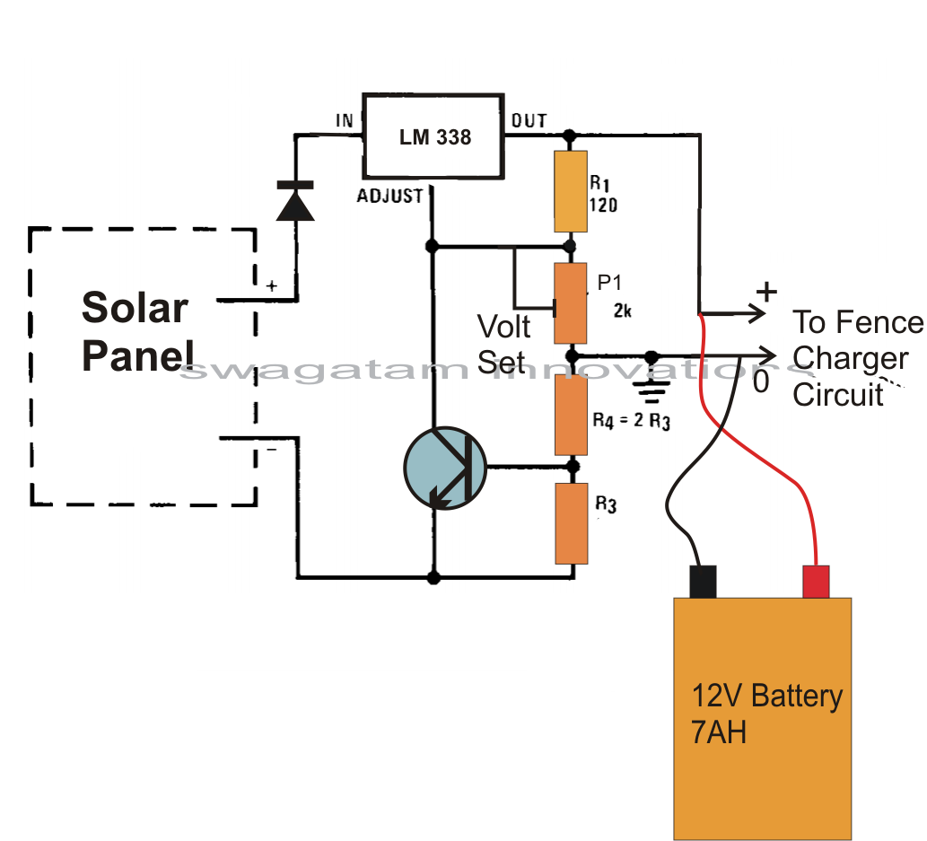
The solar panel captures sunlight and converts it into direct current (DC) electricity. This DC output is regulated by a charge controller, which ensures that the battery is charged optimally while preventing overcharging. The charge controller also provides a stable voltage to the 555 timer oscillator.
The 555 timer is configured in astable mode, generating a square wave output that switches at a predetermined frequency. This output is fed into the primary winding of the ignition coil. The ignition coil is designed to increase the voltage significantly; when the 555 timer activates the coil, it induces a high voltage in the secondary winding due to the principle of electromagnetic induction. This high voltage is then routed to the electric fence, creating a deterrent for intruders.
Additionally, the transformer plays a critical role in stepping up the voltage to the desired level. The output voltage from the transformer is typically around 220V AC, which is necessary for the operation of the ignition circuit. The system is designed to operate continuously, ensuring that the electric fence remains energized day and night, providing reliable security for the enclosed area.
In summary, the solar electric fence charger is a self-sufficient system that leverages renewable energy to provide a high-voltage output for electric fencing applications, making it an ideal solution for remote areas where traditional power sources are unavailable. The integration of solar technology with high-voltage generation components creates an efficient and effective means of protecting property from unwanted intrusions.A Fence charger or energizer is an equipment which is used for charging(electrifying) a fence or a boundary in order to protect the inside premise from human or animal interventions. Since these boundaries are mostly of large fields and parks, are normally away from the main cities, and powering them through some renewable option becomes more
suitable than from utility grids which may become difficult to acquire in such remote areas. The circuit of a solar electric fence charger explained here does not depend on traditional power source for operating, rather gets it 24/7 from a self sustained solar power conversion set up. The sudden dumping of the above high voltage inside the ignition coils primary, steps up the surge into several thousands of volts into the secondary winding of the ignition coil.
The triggering circuit consists of a IC 555 oscillator which switches the voltage obtained from the solar panel controller into the transformers input, so that the output from the transformer generates the required 220V AC for powering the ignition circuit. 🔗 External reference
Related Circuits
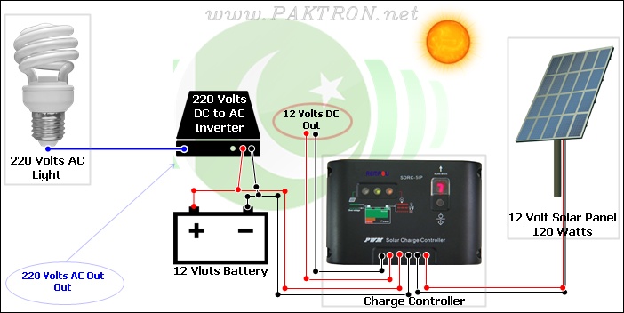
A solar charge controller is an electronic device used in solar system installations to regulate the amount of charge directed toward a battery from a solar panel. Charge controllers come in various types and ratings. The term "charge controller"...
The 220-240V AC mains source is stepped down to 9V AC by transformer X1. The transformer output is rectified by diodes D1 through D4 connected in a bridge configuration, with the positive DC voltage wired directly to the charger's...
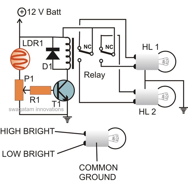
The circuit described here can be built and used in a vehicle for an automatic dipping and dimming operation of the headlamps in response to intense lights coming from opposite vehicle headlamps. This situation is often encountered while driving...
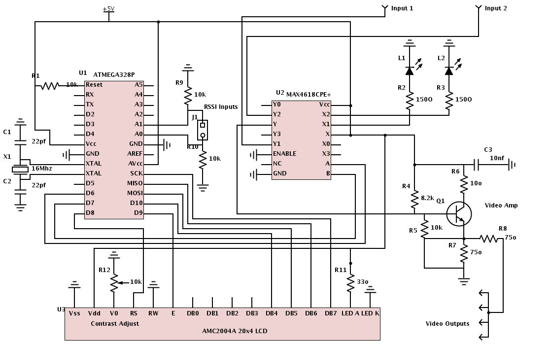
All necessary materials have been gathered to work on an Arduino-powered diversity controller. The design aims to support two inputs, although the hardware can accommodate up to four inputs, and features four amplified outputs. The diversity function will utilize...
This is a low-cost universal battery charger circuit. This circuit is designed to charge NiCd and NiMH batteries and is ideal for use in vehicles. The circuit converts mains voltage. The low-cost universal battery charger circuit is engineered to efficiently...
Schematic and description of a simple and easy-to-build NiCd and NiMH battery charger circuit that is capable of charging multiple NiCd and NiMH batteries. The circuit for the NiCd and NiMH battery charger is designed to be straightforward, allowing for...