
MARES IRIS Interface schematic circuit
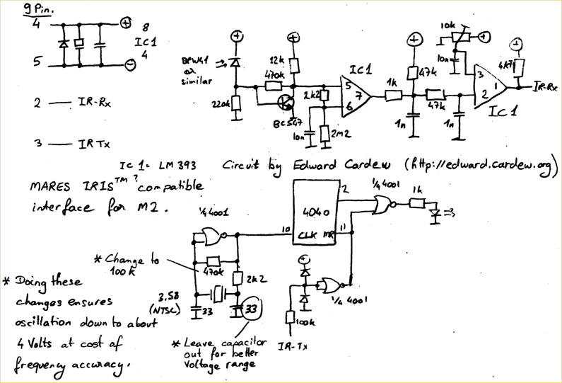
The circuit described utilizes a BPW41 infrared diode as the primary light sensor, which is capable of detecting modulated infrared signals. The receiver is powered through the RS232 port, which typically provides a voltage range sufficient for the operation of the circuit. The choice of CMOS logic chips is advantageous due to their low power consumption and ability to function effectively without the need for additional voltage regulation.
The oscillator circuit, which includes the 4001 IC, is essential for generating the necessary frequency for signal processing. The adjustment of the resistor values and the capacitor is crucial for optimizing performance, particularly when operating at lower voltages. The use of a 10k trimmer allows for fine-tuning of the output to ensure that the receiver can accurately interpret incoming data signals.
The design’s compactness is a significant advantage, as it allows for integration into small enclosures, such as a computer mouse. This aspect of the project highlights the versatility and practicality of DIY electronics in creating functional devices from readily available components. The software available on the MARES website provides the necessary tools for programming and operating the receiver, facilitating its use in various applications, including data logging for dive computers. This approach exemplifies how innovative solutions can be developed through the repurposing of existing technologies.You need a TSOP4156 which can be a tough one to get or expensive to buy. I had plenty of old BPW41 Infrared diodes so I decided to build my own receiver. The power comes from the RS232 port, make sure you have at least 5. 5 Volts or the 4001 will not oscillate well at 3. 6 MHz (Maybe you can get it to work at 5 Volts by adjusting some components. My Laptop can just manage 5. 5 Volts so I was OK. The logic chips are good old CMOS so no need to regulate to 5 Volts, more money saved. Also I found the RESET circuit of the 4040 "over the top", changing this saves yet one more NOR circuit. This circuit is realy the bare minimum in my opinion when you do not want the TSOP. The above circuit can be optimized for low voltages by changing the 470k resistor to 100k and removing the right 33pF capacitor connected to the 2k2 resistor in the oscillator (which is what I have done).
Now it oscillates down to 4 Volts but the frequency is not quite right, which is not important. Adjust the 10K trimmer for 28% of the supply voltage to obtain optimal receive bit timing. My final prototype fits in a mouse. The Software can be found on the MARES website. If like me you are a happy owner of an M2 RGBM then just pretend you have an M1 and happy dive log downloading! 🔗 External reference
Related Circuits
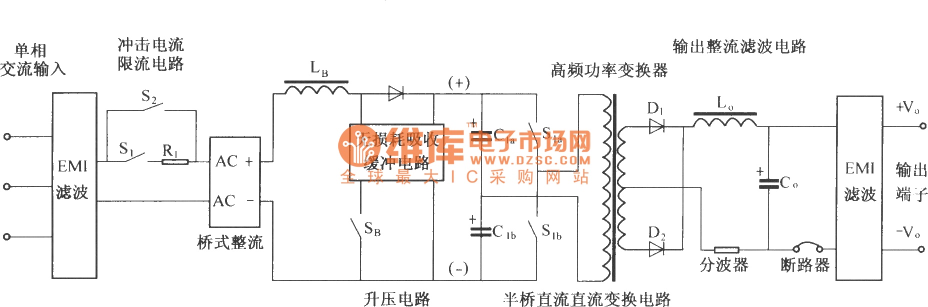
The figure illustrates a simplified schematic diagram of the main circuit DMA12. It primarily consists of the input circuit, an electromagnetic interference (EMI) filter circuit, an impulse current limit circuit, an input rectifier filter circuit, a boost/power factor correction...
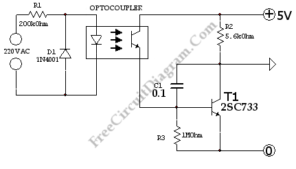
This is a simple 220V power interface circuit. This circuit is used as an interface for monitoring electrical devices and equipment using a computer. The 220V power interface circuit serves as a critical connection point between high-voltage electrical systems and...

The schematic presented is the exterior lamp circuit diagram for the 1998 Chevrolet Blazer. The wiring diagram is straightforward and should be reviewed thoroughly prior to making any modifications to the vehicle's wiring connections. The components included in this...
With the increase in the variety of modern electrical equipment for vehicles and the rise in power levels, there is a growing demand for different types of power supplies, including AC and DC sources. The power system needs to...

The basic connection circuit for the INA166 includes signal and power connections. A 0.1 µF tantalum capacitor should be used for filtering the chip's power supply terminal, and the PCB layout should be designed to position this capacitor as...

This circuit was first introduced by Signetics Corporation as the SE555/NE555 around 1971. Pin connections and functions are as follows: Pin 1 (Ground) is the most negative supply potential of the device, typically connected to circuit common when powered...