
marshall jcm800 2204 power amp
The JCM800 amplifier's design intricately balances power supply characteristics and feedback mechanisms to achieve its distinctive tonal quality. The enhanced filtering capabilities not only mitigate noise but also influence the amplifier's dynamic response during overdrive conditions. The choice of a 4-ohm tap for negative feedback, along with the increased feedback resistor value, plays a crucial role in shaping the amplifier's response to input signals, allowing for a more aggressive clipping behavior that is characteristic of rock and high-gain applications.
The power supply design is critical to the overall performance of the JCM800. The use of a high-voltage transformer and substantial filter capacitors ensures that the amplifier can maintain stable operation under varying load conditions. The calculated voltages at different points within the circuit, including the EL34 plates and screens, indicate a well-designed power stage capable of delivering the necessary power while managing thermal dissipation effectively. The ripple attenuation figures highlight the advancements made in filtering technology, which contribute to the amplifier's clarity and sustain.
Furthermore, the dynamic response of the amplifier under overdrive conditions is a result of the interplay between the power transformer, rectifier, and filter components. The observed voltage sag and transients provide insight into the amplifier's behavior during high-demand situations, which can significantly affect the musical output. This understanding is crucial for musicians and audio engineers seeking to exploit the unique characteristics of the JCM800 in live performances or studio recordings. The design choices made in the JCM800 reflect a deep understanding of tube amplifier behavior, resulting in a powerful and versatile tool for sound creation.The JCM800 power amp follows a long lineage of classic amplifiers that include the Fender Bassman 5F6-A, the Marshall JTM45, the Model 1962 "Bluesbreaker, " and the Model 1987 "Plexi. " It has substantially more power supply filtering than any of its ancestors, which contributes to a slower, more sustained dynamic as the amp is overdriven.
We`ll exa mine the effects here. The amp also derives negative feedback from the 4-ohm output transformer tap instead of the Plexi`s 8-ohm tap and doubles the feedback resistor connecting it to the phase inverter. We`ll look at these artifacts as well. The 345-0-345 volt RMS power transformer creates 488 volts DC if there is no load or rectifier loss. If we assume 5 percent sag and less than 5 volts DC loss across the output transformer primary, then we get about 460 volts at the EL34 plates.
(For Class AB and a solid state rectifier there is little sag at idle. ) A drop of less than 5 volts across the choke gives us at least 455 volts at the top of the 1k Screen resistors. Let`s assume about 5mA screen current and see if this holds up under additional scrutiny. That creates a 5-volt drop across the screen resistors to put 450 volts at the screens. The blue curve shown here on the transfer characteristics is our estimate for a 450 volt screen. Maximum plate dissipation for the EL34 is 25 watts, so if we bias the amp at 70 percent, we get 18 watts, making the idle plate current (18)/(450) = 40mA.
This is the red line which intersects the curve at a grid voltage of minus 40 volts. By examining the transfer characteristics for screen current at the bottom of the graph we observe that the idle screen current is well under 10mA, well within the plus-or-minus 20 percent standard of tube amp design, so our original estimate for screen voltage appears reasonable. According to our LC Ripple Filter Calculator there is 64dB of ripple attenuation for 50-Hertz AC across the choke.
For 60-Hertz power it is 67dB. This is substantially more than earlier Marshalls. The JTM45, Bluesbreaker, and Plexi have 20 Henry chokes. The Bassman uses only 10 Henries. Filter capacitor values also increased through the lineage as the price of high-voltage electrolytics dropped. The JTM45 used 32 microfarads on each side of the choke. The JCM800 uses 100 microfarads. The direct result is substantially less hum in the plate and screen supplies. What is often overlooked, however, is the effect of these changes on the dynamics of the power stage when the amp is overdriven.
The resistances in the power transformer, the internal plate resistance of the rectifier tube, and the resistance in the choke cause the DC voltage supplying the power amp screens to sag exponentially. The choke and filter capacitors also interact with one another to cause the voltage to oscillate somewhat, as shown in the following figure.
1 The graph shows power supply voltage sag in the Fender Bassman 5F6-A over the first 500 milliseconds after the onset of a full-power signal. The red, solid curve is the actual sag. The blue, dotted curve shows the first order component, whose drop in voltage is determined by the increase in current demand and the characteristics of the power transformer and rectifier.
The time period over which the sag takes place depends mostly on the size of the choke and filter capacitors. The JCM800`s larger filter reacts more slowly. The black, dashed curve shows the second-order transient, which is caused by the interaction of the choke with the capacitors on either side.
This transient is more prominent and decays less quickly in the JCM800. The JCM800 derives negative feedback from the 4-ohm output transformer tap instead of the Model 1987`s 8-ohm tap. It also raises the feedback resistor connecting it to the phase inverter from 47k to 100k. Both factors combine to lower negative feedback by a factor of 3. 2 Overdriving the power amp causes output clipping and clampi 🔗 External reference
Related Circuits
An inverting mode amplifier is required for precision accelerometers due to their typical charge output characteristics. This amplifier is utilized to convert charge into voltage. An inverting mode amplifier is a critical component in applications involving precision accelerometers, which often...
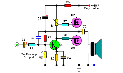
This project includes a preamplifier, tone controls, a regulated DC power supply, and delivers 18 watts into an 8-ohm load and 30 watts into a 4-ohm load. The circuit design comprises several key components that work together to create...
The voltage Vc1 increases linearly when the pull-up resistor RA in the monostable circuit is replaced with a constant current source, resulting in a linear ramp. The circuit for generating the linear ramp and the corresponding waveforms are illustrated...
The video amplifier depicted in the diagram is a widely recognized design that is both simple and highly effective. However, the transistors are susceptible to damage if the potentiometers (black level and signal amplitude) are set to their extreme...
Each power supply, whether linear or switching, operates in at least two modes: constant voltage (CV) and constant current (CC). The power supply can function in either mode, with the other serving as a protective mode for both the...
60W Bass Amplifier. It features low-cut and bass controls. The output power is 40W on 8 Ohm loads and 60W on 4 Ohm loads. An amplifier circuit diagram is provided. The 60W bass amplifier is designed to deliver robust audio...