
Marty I have a 1991 350SDL that has the center vent not
A comprehensive understanding of the vacuum system in the 1991 350SDL is essential for diagnosing the center vent airflow issue. The vacuum system plays a critical role in controlling various actuators that manage air distribution within the vehicle's HVAC system. The presence of a capped vacuum line suggests a potential disruption in the system that could affect airflow. The actuator's functionality can be inferred from the behavior of the air distribution; however, the complete diagnosis requires a thorough inspection of the vacuum lines and components.
To begin troubleshooting, it is necessary to locate the vacuum pump and ensure it is generating sufficient vacuum pressure. This can be accomplished by measuring the vacuum at the source, which may involve checking both the small rubber line and the metal fitting connected to the pump. A vacuum gauge should be utilized to quantify the vacuum pressure, with a minimum of 18 inches of vacuum being the target at the switchover valve (Y7). The use of a hand vacuum pump will facilitate testing of individual vacuum elements; any components that do not hold vacuum should be replaced.
The identification of the vacuum line routing is critical. The red/green hose that connects to the check valve should be traced to confirm its integrity and connection to the vacuum valve on the injection pump. If the check valve is missing, it may need to be replaced to restore proper vacuum functionality. Additionally, the reddish hose from the power brake booster should be examined to determine its role in the overall vacuum system.
Accessing the HVAC components may require removing obstructions, such as the large metal vent tube, to reach screws and connectors. Proper tools and a systematic approach will be necessary to navigate the complexities of the vacuum system and ensure that all connections are secure and functional. This methodical approach will aid in diagnosing the root cause of the airflow issue and facilitate the necessary repairs to restore optimal HVAC performance in the vehicle.A 1991 350SDL that has the center vent not blowing air issue. However, When I get on it and the revs go high, air does move from the defrost vents to the center vents. Does that mean that the actuators are ok and I have a leak somewhere else or does that mean I still need new actuators.
Either way, I`ll need your help to track it down and fix it. Not that I know of. I have only had it for about 6 months. Here is what I can tell you. The transmission will sometimes hold a gear instead of upshifting until I lift off the gas. I brought it to a mechanic and he felt the transmission shifted well and it was a vacuum issue. The second thing is that the vacuum valve off of the injection pump has some vacuum tubes that go to a valve near the drivers wheel well. That same valve has some lines that then go into the inside of the car. One of those lines is disconnected and capped. Today my mechanic said I needed to replace 4 valves in the dash in order to be able to get my AC to blow colder.
But I do not believe he saw the capped line. I think he just thought that the valves were bad (which they might be). The last thing is that the air does in fact come out of the center vents when I floor the car and the revs go up for a few seconds. After I lift off the gas, the air flow will go back to the defrost vents. I believe I can hear the flaps going back. I really have no way to check for a vacuum leak and having previously seen a vacuum diagram it looked like there must have been hundreds of lines that probably are not easy to get to.
Ok, let`s start with a vacuum schematic of the system and the location of the main switchover valve. Step one is to be sure we have adequate vacuum from the vacuum pump going to the switching valve (Y7). You can start by checking it under the hood at the source. Then you`ll need to access the valve alongside the right side of the center console. You should have at least 18" of vacuum at the valve. All of your testing can be done from the valve. You`ll need a hand vacuum pump to apply vacuum to the various vacuum elements. You`ll then need to replace any vacuum elements that are leaking. I have a few questions. When you say to check the vacuum pump at the source under the hood, do you mean right at the pump The pump has two commectors.
A small rubber line and a metal fitting with a tube. Do you want me to check one of these And if so, what type of tool do I need to buy to check this I don`t have a hand vacuum pump but finding one should not be hard. Any recommendations Also, I will need some sort of gauge to hook up to check vacuum and I am kind of thinking in my mind how you would hook up the vacuum pump and the gauge at the same time.
I guess it would have to be serially. I am pretty good at mechanical work, but I have not really done anything with vacuum and don`t have any of that stuff. Actually - I may have a vacuum gauge. I`m going to go and try to find it. Just got back from Harbor Freight with a Mityvac MV8000 hand vacuum kit. The gauge is built right in so I don`t have to worry about that. When you have time to get back to me on my last questions I can go ahead and try using it. I am trying hard to find the source of the vacuum hose to Y7 and have been over the EPC and WIS, but am still confused.
If I read it right, WIS says that I am to connect a vacuum source to a red/green hose that is attached to a check valve. I do see a red/green hose but there is no check valve on it. It goes to one of the connectors on the vacuum valve on the injection pump. I do see a reddish hose that looks like it comes off what may be a check valve off of the power brake booster, but I am not sure if I should be checking one of these or not.
Got to my first problem. I have the bottom of the airbag cover off, got the red airbag connector disconnected but the large metal vent tube is in the way of anything else and I can`t seem to find the screws to get it o 🔗 External reference
Related Circuits
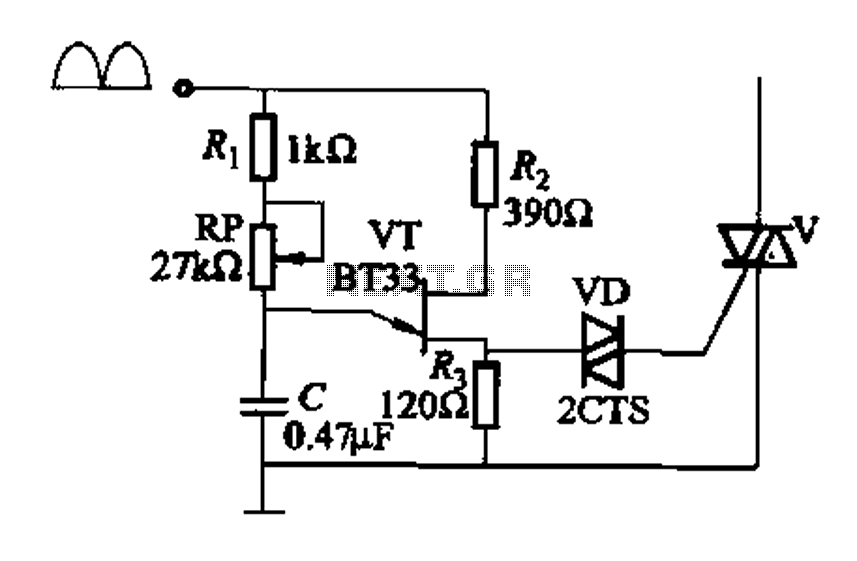
Figure 16-29 (a) illustrates the trigger output through a resistor R2, while Figure 16-29 (b) depicts the integration of a programmable unidirectional transistor (PUT) trigger circuit. The adjustable potentiometer RP can modify the conduction angle of the TRIAC to...
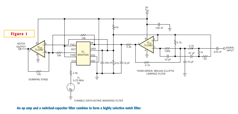
Although you can obtain universal, resistor-programmable switched-capacitor filters that are configurable as notch filters, most cannot operate at bandwidths higher than 100 kHz. Further, the typically 16- to 20-pin packages do not include a continuous-time, antialiasing filter to prevent...
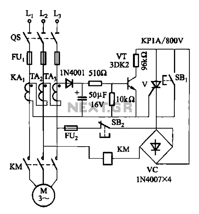
Both circuits are used to control the thyristor contactor KM action to overcome the break phase protection relay prone to malfunction or refuse to move, and enhance the sensitivity and reliability of the protection device. The described circuits are designed...
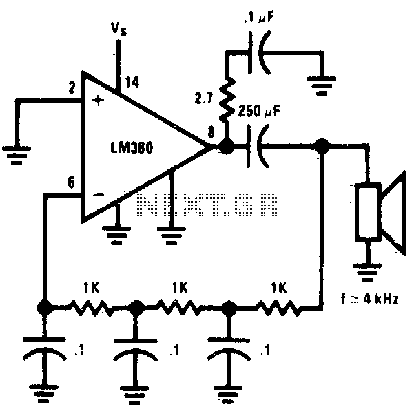
The circuit utilizes a simple RC network to generate a very high-pitched tone from a miniature speaker. With the specified component values, the circuit oscillates at a frequency of 3 kHz and drives a miniature 2W speaker at an...
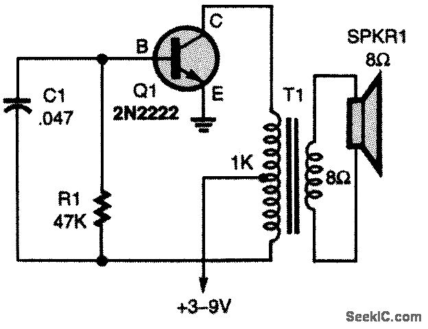
The oscillator circuit employs a center-tapped transistor output transformer that functions as a load for the collector of Q1, provides a feedback signal to the base, and acts as the output winding to drive the speaker. Resistor R1 supplies...
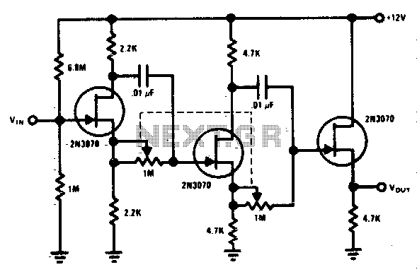
Each stage provides a phase shift ranging from 0° to 180°. By combining two stages, a total phase shift of 0° to 360° can be achieved. This circuit is powered by AC and DC supplies, specifically designed as a...
Warning: include(partials/cookie-banner.php): Failed to open stream: Permission denied in /var/www/html/nextgr/view-circuit.php on line 713
Warning: include(): Failed opening 'partials/cookie-banner.php' for inclusion (include_path='.:/usr/share/php') in /var/www/html/nextgr/view-circuit.php on line 713