
Master/Slave Switch

This circuit operates as a master/slave controller, utilizing a solid-state relay to manage the power state of connected devices based on the current draw of a master device. The design incorporates a zero-crossing detection feature to enhance safety and reduce electromagnetic interference during switching events. The integration of the triac drive circuitry within the relay minimizes the need for external components, facilitating a more compact design that is easier to implement in various applications.
The current sensing function is achieved through diodes D1, D2, D3, and D4, which detect the current flowing to the master device. When the master device is powered on, these diodes generate a corresponding voltage across capacitor C2, which triggers the solid-state relay to activate the slave equipment. The use of a Schottky diode for D5 is particularly advantageous, as it ensures minimal voltage drop, thereby improving the circuit's efficiency and responsiveness.
The RC network formed by R1 and C1 serves a dual purpose: it not only protects the relay from voltage spikes that could occur due to fluctuations in the mains supply but also helps to filter out noise, ensuring stable operation. The overall design must take into account the high voltages present in the circuit, which necessitates careful layout considerations and the implementation of appropriate safety measures, such as the use of a plexiglass shield for the LED indicator.
In summary, this circuit exemplifies a practical solution for controlling multiple devices within a home or audio environment, leveraging modern solid-state technology to achieve reliable and efficient operation.In this age of enlightenment any sort of relationship that could be described as master/slave would be questionable but for the purposes of this circuit it gives a good idea of how it functions. The circuit senses mains current supplied to a master` device and switches slave` equipment on or off.
This feature is useful in a typical hi-fi or home c omputer environment where several peripheral devices can all be switched on or off together. A solid-state relay from Sharp is an ideal switching element in this application; a built-in zero crossing detector ensures that switching only occurs when the mains voltage passes through zero and any resultant interference is kept to an absolute minimum. All of the triac drive circuitry (including optical coupling) is integrated on-chip so there are very few external components and no additional power supply necessary.
This makes the finished design very compact. Diodes D1, D2, D3 and D4 perform the current sensing function and produce a voltage on C2 when the master equipment is switched on. A Schottky diode is used for D5 to reduce forward voltage losses to a minimum. The circuit is quite sensitive and will successfully switch the slave even when the master equipment draws very little mains current.
The RC network formed by R1 and C1 provides some protection for the solid-state relay against mains-borne voltage transients. This circuit is connected to the mains. it is important to be aware that the chip has lethal voltages on its pins and all appropriate safety guidelines must be adhered to!
This includes the LED, for safety it must be fitted behind a transparent plexiglass shield. 🔗 External reference
Related Circuits
A precision oscillator can be constructed using a quartz crystal; however, with appropriate component selection, it is also possible to build one using an RC (resistor and capacitor) circuit. An RC oscillator generates an oscillating signal through the use of...
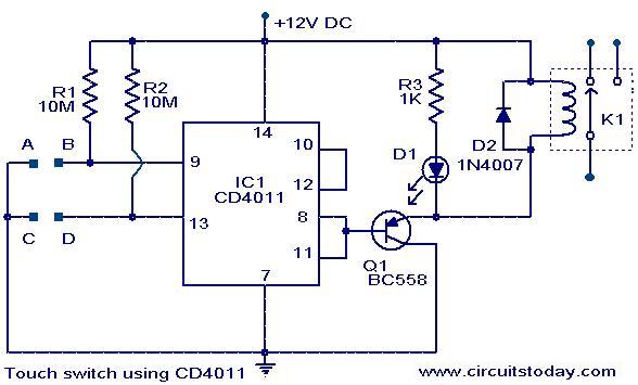
The following circuit illustrates a Touch Switch Circuit Diagram. This circuit is based on the CD4011 IC. Features include R1 and R2, which are the logic gates of the circuit. The Touch Switch Circuit utilizes the CD4011 integrated circuit, which...
This module is an essential addition to the Modular Preamplifier Control Center when more than two sources need to be connected to the preamplifier chain. Four high-level inputs can be selected using SW1 and routed to the output. The...

A 3x3-inch piece of circuit board, or a similarly sized metal object, serves as the pick-up sensor connected to the gate of Q1. A 100 MΩ resistor, R2, isolates Q1's gate from R1, ensuring that the input impedance remains...

The current vehicle, a Pajero, has been modified for dual fuel operation, utilizing both petrol and gas. It is essential to operate the vehicle on petrol at regular intervals to prevent clogging of the injectors. This circuit facilitates starting...
The Zero Volt Diode (ZVD) is a circuit useful in various applications, including solar chargers of all types. It is a novel circuit where a power MOSFET functions as a very low voltage drop diode, switching states at 0V...