
Power switching circuits
The schematic for the Zero Volt Diode circuit includes a solar panel connected in series with the MOSFET (2N7000), complemented by an NPN and PNP transistor arrangement. The solar panel's positive terminal connects to the drain of the MOSFET, while the source connects to the capacitor or battery. The gate of the MOSFET is controlled by the NPN transistor, which is clamped when the capacitor voltage exceeds 0.6V. The PNP transistor is connected to the negative terminal of the solar panel, ensuring that when the voltage drops below 0V, it activates the circuit, allowing current to flow from the solar panel to the capacitor. The circuit design ensures that the MOSFET operates efficiently, minimizing voltage drop and maximizing energy transfer from the solar panel to the storage element. The overall configuration provides a robust solution for solar charging applications, particularly in scenarios where efficiency and minimal energy loss are paramount.The Zero Volt Diode (ZVD) is a circuit useful in a variety of applications including solar chargers of all types. It is a novel circuit in which a power MOSFET acts like a very low voltage drop diode that switches state at 0V and which is used to conduct negative current from drain to source.
In D1 type solar engines, a low loss diode can be used to charge a cap to the open circuit voltage of the solar cell and used in solar battery chargers, the battery is charged at the maximum rate when the source voltage is highest. The diode must be used in series with the solar panel or else the cap or battery would discharge through the solar panel when the panel voltage drops below the stored voltage.
The diode or equivalent polarity sensitive switch is therefore essential to solar chargers. Most diodes used in BEAM SEs and solar chargers are Silicon diodes like the 1N4001 which have a voltage drop of 0. 6V to 1V at currents up to 1A. More efficient diodes for currents form >100mA to tens of amps applications are the Schottky type rectifiers with a voltage drop of from 200mV to 1000mV depending on the current level.
For <100mA applications a Germanium diode can used with 200mV or less drop. This voltage drop issue is important in competition solar engines since you would like to have the maximum voltage to charge the cap and supply the load (low diode drop) and keep the charge stored on the cap when the lightlevel drops (leakage current cut off) and the SE triggers. Moreover, since the energy in the cap is proportional to the square of the voltage even the small voltage drop of a diode reduces available energy.
One obvious simple improvement over the original D1 design is to substitute a Ge 1N34A diode (Radio Shack) instead of the Si 1N4001 diode. An ideal diode would have zero voltage drop. While a straight hookup of the solar cell has minimum voltage drop it leaks if the light drops and any real diode has a forward voltage drop.
What to do The solution is to use a MOSFET as a rectifier just like the synchronous rectifier applications in voltage converters. The MOSFET should be switched ON when the solar voltage is larger than the capacitor or battery voltage and switch OFF when the solar voltage is lower than the stored voltage.
Here is a little design for charging capacitors from solar cells with zero voltage drop at the end of the charge cycle. It can be easily scaled to higher currents by changing the 2N7000 for a larger MOSFET. If a parallel load is present, the circuit also delivers maximum voltage with minimum insertion loss from the solar cell.
The MOSFET turns on when the voltage difference is zero and turns off when the solar voltage drops less than 100mV below the cap or battery. The NPN transistor is normally ON when the cap voltage is more than. 6V and this clamps the gate of the 2N7000 which is turned OFF. The PNP transistor is connected to the negative terminal of the solar panel and when the voltage on that terminal drops below 0V the PNP turns ON.
This in turn turns the NPN OFF and the 2N7000 turns ON. MOSFETs have an interesting characteristic in that they act like bi-directional switches, so the 2N7000 is perfectly happy to have it`s drain conduct a negative current to the 0V line. When the voltage on the negative terminal of the solar panel is more positive than 0V the PNP turns OFF and the NPN ON and the 2N7000 turns off with the drain voltage positive with respect to the source voltage and 0V line.
Since the 2N7000 does not turn on until the gate voltage is more than 2V (in practice: higher according to the data book) a logic FET with a lower gate turn on voltage would be preferred. In any case the MOSFET has a integral reverse diode from drain to source which will carry the current until the voltage on the cap reaches 2V at which point the MOSFET turns on and the forward voltage drops to a few 10s of mV.
🔗 External reference
Related Circuits
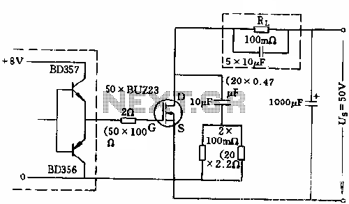
The circuit employs 50 BUZ23 field effect transistors (FETs) arranged in parallel, with a tube blocking voltage of 100V. The control power required is minimal, eliminating the risks associated with second breakdown and the positive temperature coefficient phenomenon in...
One still designing that it uses in the exit transistor of technology V-mosfet. This transistors to us offer a lot of virtues concerning the simple bipolar transistors, as high speeds, thermic stability, low distortion etc. Beyond this circuit use...
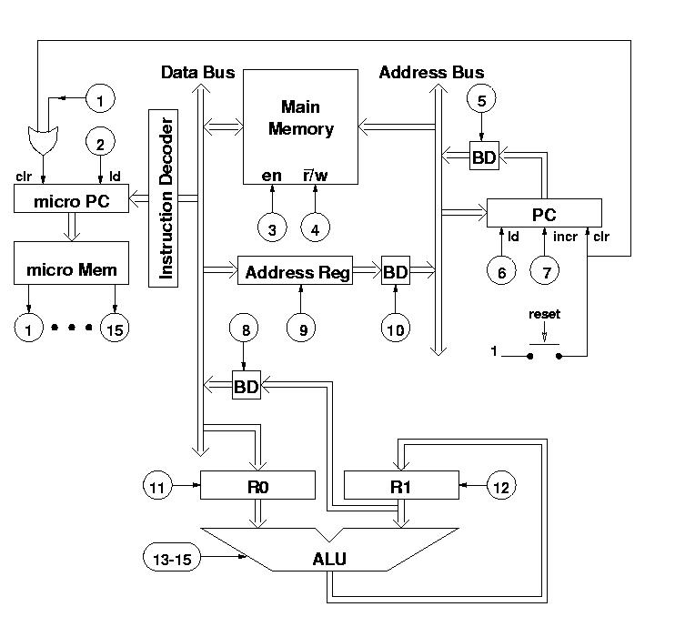
The diagram features a micro memory capable of storing up to 64 different addresses, each containing 15 bits, referred to as micro operations (MOPs). These MOPs govern all functions of the computer. Adjacent to the micro memory is the...
The range of this FM transmitter is approximately 100 meters when powered by a 9V DC supply. The circuit consists of three stages. The first stage is a microphone preamplifier. The FM transmitter circuit is designed to convert audio signals...
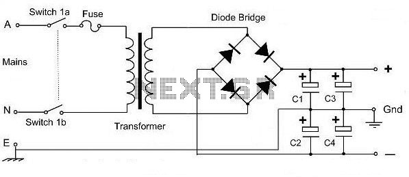
This is a basic dual polarity power supply circuit diagram. It requires the following components: a center-tapped transformer, four diode rectifiers (or one diode bridge), and four electrolytic capacitors. The value of each component is essential for the circuit's...
Class-A is ideal for this application, since headphones are such an intimate way of listening. An amplifier for 'phones should be as clean and free from crossover distortion as possible, and must also be quiet. A background of hiss...
Warning: include(partials/cookie-banner.php): Failed to open stream: Permission denied in /var/www/html/nextgr/view-circuit.php on line 713
Warning: include(): Failed opening 'partials/cookie-banner.php' for inclusion (include_path='.:/usr/share/php') in /var/www/html/nextgr/view-circuit.php on line 713