
petrol gas switch for pajero

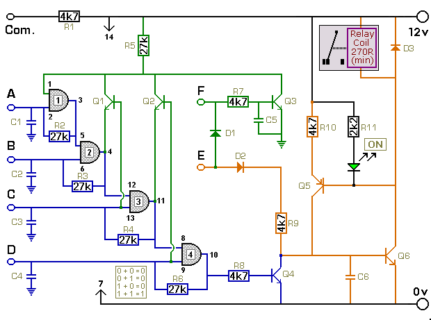
The described circuit serves as an effective solution for managing the dual fuel system in the Pajero, ensuring that the vehicle can transition seamlessly between petrol and gas while maintaining optimal performance and injector health. The use of an LM324 dual op-amp allows for precise control and monitoring of vehicle speed, enabling the system to respond dynamically to driving conditions.
The speed sensor provides a real-time voltage output that correlates with the vehicle's speed. This voltage is conditioned by the filter network, which smooths out any fluctuations and provides a stable DC signal to the comparator. The comparator's output is configured to trigger at a specific voltage determined by the trimpot, allowing for customization of the speed threshold.
Transistors Q1 and Q2 function as switches, controlling the activation of the relay based on the conditions of speed and brake application. The relay serves as the mechanism to switch the fuel source from petrol to gas, ensuring that the vehicle operates efficiently and effectively under varying conditions. The integration of the brake light circuit into the system provides an additional layer of control, ensuring that the transition to gas occurs only when it is safe and appropriate to do so.
Overall, this circuit design exemplifies a practical application of analog electronics in automotive systems, providing a reliable method for managing dual fuel operation while safeguarding engine components from potential issues related to fuel type and injector maintenance.My current vehicle, a Pajero, was modified for dual fuel - ie, petrol and gas. However, it`s necessary to run the vehicle on petrol at regular intervals to stop the injectors from clogging up. This simple circuit allows the vehicle to be started using petrol and then automatically switches it to gas when the speed exceeds 45km/h and the brake peda
l is pressed. Alternatively, the vehicle may be run on petrol simply by switching the existing petrol/gas switch to petrol. You can also start the vehicle on gas by pressing the brake pedal while starting the vehicle. The circuit is based on an LM324 dual op amp, with both op amps wired as comparators. It works like this: IC1a buffers the signal from the vehicle`s speed sensor and drives an output filter network (D1, a 560kO resistor and a 10 µF capacitor) to produce a DC voltage that`s proportional to the vehicle`s speed.
This voltage is then applied to pin 5 of IC1b and compared with the voltage set by trimpot VR1. When pin 7 of IC1b goes high, transistor Q1 turns on. This also turns on transistor Q2 when the brake pedal is pressed (pressing the brake pedal applies +12V from the brake light circuit to Q2`s emitter). And when Q2 turns on, relay 1 turns on and its contacts switch to the gas position. Trimpot VR1 must be adjusted so that IC1b`s pin 7 output switches high when the desired trigger speed is reached (ie, 45km/h).
In effect, the speed signal is AND`ed with the brake light signal to turn on the relay. The vehicle has been running this circuit for several years now and is still running well, with no further injector cleans required. 🔗 External reference
Related Circuits
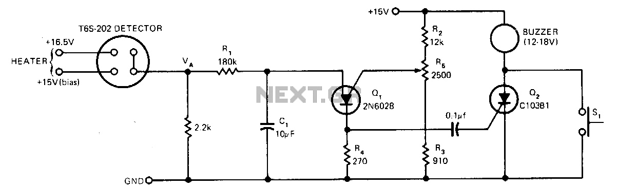
The sensor operates based on the selective absorption of hydrocarbons by an n-type metal-oxide surface. The device features a heater designed to eliminate hydrocarbons once smoke or gas is no longer detected in the immediate vicinity, allowing for reuse....
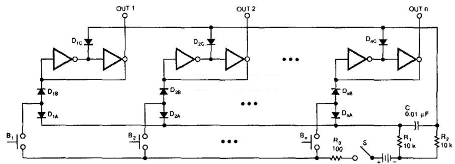
This switching circuit functions as a bank of interlocked mechanical switches. Activating one of the buttons latches its corresponding output while unlatching a previously selected output. A pair of inverters creates a latch for each output. For instance, pressing...
The key connected to "E" is used to energize the relay, while the four keys connected to A, B, C, and D are used to de-energize it. All other keys on the keypad are connected to "F". When "E"...
This is a remote on-off switch circuit. This circuit allows the use of a small switch to control larger AC currents from high-power devices. The remote on-off switch circuit operates by utilizing a low-power control signal to manage a high-power...
A 1984 F-350 crew cab with a 460 engine has a malfunctioning fuel gauge and is unable to pump fuel from the front tank. The initial troubleshooting steps included replacing the switch in the dashboard and the switch on...
This circuit can be utilized as a replacement for the single current-limiting resistor typically found in low-cost battery chargers. The alternative presented here is advantageous because it prevents the premature failure of nickel-cadmium (NiCd) batteries, which often occur after...