
maximite stepper motor interface
The circuit utilizes the Maximite microcomputer to efficiently control a stepper motor through a series of output pins connected to a ULN2003 Darlington transistor array. The arrangement of the circuit allows for precise bidirectional control of the motor by switching the current through its windings. The four output pins of the Maximite are utilized to control each motor, with the ability to expand the setup for multiple motors.
The ULN2003 acts as a driver for the motor, where each output pin corresponds to a specific motor winding. When a Maximite output pin goes high, it activates the respective Darlington transistor, allowing current to flow through the motor winding. This arrangement ensures that when a pin is high, the corresponding transistor is off, preventing current flow and allowing for controlled stepping of the motor.
The design includes a PNP Darlington transistor (Q1) that regulates the current flowing through the motor windings. The base of Q1 is driven by a resistive divider, establishing a base voltage that enables the transistor to operate efficiently. This configuration helps achieve a maximum current of approximately 450mA, determined by the voltage drop across the resistor in the circuit.
To ensure the reliability of the transistors under operation, a heatsink is recommended for Q1 to dissipate the heat generated during operation, especially at higher currents. The circuit also incorporates protective measures against back-EMF generated when the motor is turned off. The internal diodes of the ULN2003 provide a path for the back-EMF to safely return to the power supply, thus avoiding damage to the transistors.
Manual control of the motor direction is facilitated through a toggle switch or pushbutton connected to the Maximite's input pin, allowing for user interaction. The timing of the output pin activation determines the speed of the motor, with a defined sequence for forward and reverse operations, as detailed in the accompanying documentation. The program code necessary for operation is accessible for download, providing a complete solution for controlling stepper motors using the Maximite microcomputer.This simple circuit and program listing allows the Maximite microcomputer (SILICON CHIP, March-May 2011) to control a stepper motor. It could be expanded to allow for the control of multiple motors, with four of the Maximite`s external I/O pins used to control each motor with identical driver circuits.
A ULN2003 Darlington transistor array (IC1) s witches current through the stepper motor`s two windings in either direction. When one of the four Maximite output pins (8, 12, 16 & 20, corresponding to I/Os 19, 17, 15 & 13) goes high, the corresponding output pin on IC1 goes low, sinking current through a motor winding. Conversely, when these pins are high, the corresponding Darlington transistor is off and so no current flows through that portion of the winding.
The centre tap of each motor winding is connected to a current source comprising PNP Darlington transistor Q1 and some resistors. The maximum current is determined by the resistive divider driving its high-impedance base, setting the base voltage to around 9.
1V when it is fully on. By adding Q1`s base-emitter voltage (1. 4V at 0. 5A, as per the data sheet) we can determine that there will be around 1. 5V across the 3. 3O resistor (12V - 10. 5V), resulting in a current of 1. 5V G· 3. 3O = ~450mA. Transistor Q1 must be fitted with a medium-sized flag heatsink (Jaycar HH8504, Altronics H0637) or larger to handle its maximum dissipation of (10. 5V - 4. 9V) x 450mA = 2. 5W. When one of the Darlington transistors switches off and current flow through the corresponding motor winding ceases, the inductive winding generates a back-EMF current which causes the voltage across that winding to spike.
IC1 has internal free-wheeling diodes from each output to the COM pin, which is connected to the +12V supply. The back-EMF current flows back into the power supply and the voltage spikes are clamped at about 12.
7V, so that the Darlington transistors do not suffer collector reverse breakdown, which might damage them. A 470 µF capacitor provides supply bypassing for the motor while a 47kO pull-up resistor and toggle switch/pushbutton S1 drives input pin 9 of the Maximite, allowing manual control of the motor direction.
Table 1 shows the sequence in which the output pins are driven to turn the motor forward; the steps are run backwards for reverse operation. The delay between the steps determines the speed at which the motor rotates. The source code of the sample program is available for download from the SILICON CHIP website (maximite_stepper_motor.
bas). 🔗 External reference
Related Circuits
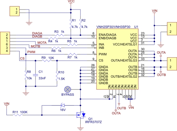
Need more current? If you have a larger motor ready for use, the Pololu High Current Motor Driver Board 14A 6V-16V is the ideal solution. Connect three digital lines to your microcontroller (five if error condition feedback is desired),...
In single-phase AC induction motors, commonly found in refrigerators and washing machines, a start winding is utilized during the initial starting phase. Once the motor reaches a specific speed, this winding is deactivated. The start winding operates slightly out...

A bidirectional H-bridge DC motor control circuit is illustrated. The circuit utilizes the L298 integrated circuit from ST Microelectronics. The L298 is a dual full-bridge driver that supports a wide operating voltage range and can manage load currents up...
Below is a block diagram of modern automated systems that incorporate closed-loop feedback for motion control. They typically include a servo system that consists of various components. Automated systems utilizing closed-loop feedback mechanisms are designed to enhance precision and responsiveness...
Connect any I2C client chip (such as temperature sensors, analog-to-digital converters, displays, or relay drivers) to your PC via USB quickly, easily, and affordably. Drivers are available for both Linux and Windows operating systems. The described system facilitates the integration...
Sometimes when experimenting with different soundcards and MIDI interfaces it is useful to see if there is some data going in MIDI interface. This can be easily tested with this adapter, which converts the midi signals to visible light...
Warning: include(partials/cookie-banner.php): Failed to open stream: Permission denied in /var/www/html/nextgr/view-circuit.php on line 713
Warning: include(): Failed opening 'partials/cookie-banner.php' for inclusion (include_path='.:/usr/share/php') in /var/www/html/nextgr/view-circuit.php on line 713