
transistors Problems with Wien Bridge oscillator circuit simulation in Mutisim
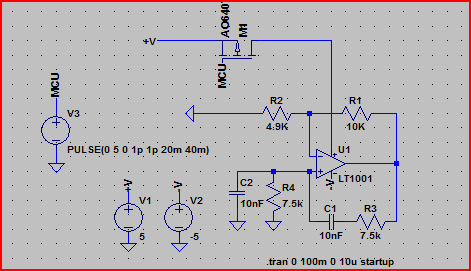
The Wien bridge oscillator is a type of electronic oscillator that generates sine waves. It consists of a bridge circuit with resistors and capacitors arranged in a specific configuration that determines the frequency of oscillation. In this case, the target frequency is set to 2.1 kHz. The oscillator's output can be adjusted by varying the resistance in the feedback loop, which is typically achieved using a light bulb or a thermistor for automatic gain control, but can also be switched using a transistor.
To integrate a transistor switch into the circuit, it is important to ensure that the transistor is correctly biased to operate in the active region when the PIC microcontroller sends a signal. The transistor should be capable of handling the required current and voltage levels, and its base should be connected to a digital output pin of the PIC. A pull-down resistor may be necessary to ensure that the transistor remains off when the microcontroller output is low.
The discrepancy between the expected output of 5.0 V peak-to-peak and the measured 3.0 mV in the simulation may stem from several factors. First, ensure that the resistors and capacitors used in the circuit are of appropriate values to achieve the desired frequency and gain. The gain of the amplifier stage must be sufficient to overcome the losses in the circuit. Additionally, check for any unintended loading effects caused by the transistor or the microcontroller, which may dampen the oscillation.
It is also advisable to verify the stability of the power supply voltage provided to the circuit, as fluctuations can significantly affect the output. The design may require tuning of the resistor values in the feedback network to achieve the desired amplitude of oscillation. Lastly, ensure that the simulation parameters in Multisim accurately reflect the real-world components being used, as discrepancies in component models can lead to significant differences in performance.
In conclusion, careful consideration of the circuit design, component values, and simulation settings will be crucial in resolving the issues with the Wien bridge oscillator and achieving the desired output voltage.Build a Wien bridge oscillator that oscillates at 2. 1kHz and that can be switched on by a transistor. The reason for me placing a transistor switch in the circuit is so that I can turn the oscillator on and off from a PIC MCU. However, when I build the simulation in multisim, I get an DC output voltage of 3. 0mV and an. I want an output voltage of 5. 0V p-p, so can anybody explain to me what the problem with this circuit is Any help would be much appreciated. 🔗 External reference
Related Circuits
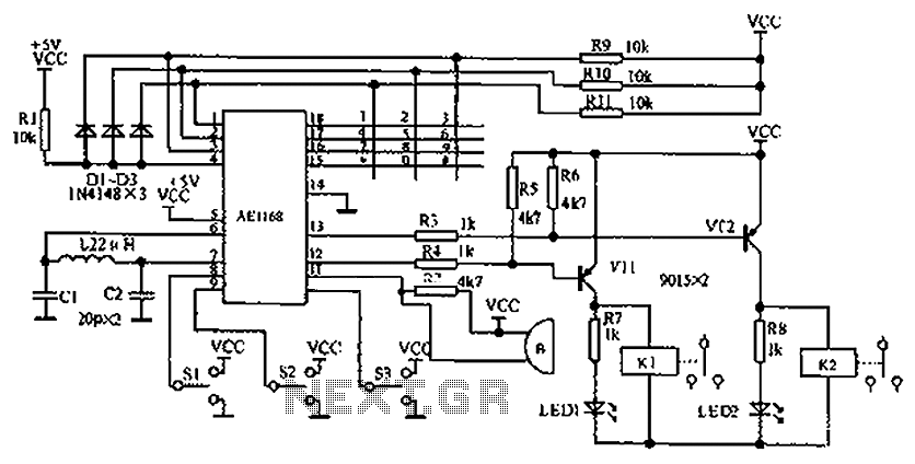
The circuit diagram represents an enhanced lock system, the AE1169, which is an upgrade of the AE1168 model. When the lock button is pressed, the AE1168 utilizes a keyboard scanning method to identify the corresponding button. Based on the...
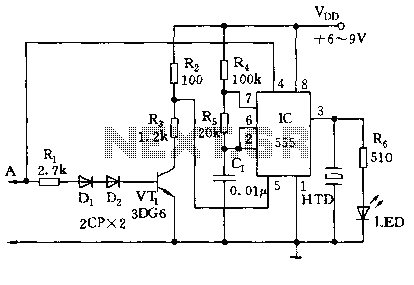
The circuit utilizes a 555 timer along with resistors R4, R5, and capacitor C1 configured in a controllable multivibrator mode. This setup forces the reset terminal (pin 4) to a specific state, allowing for control of the external logic...

A PLL oscillator, or phase-locked loop oscillator, is a control method that compares a controlled system or plant to a reference signal. A phase-locked loop (PLL) oscillator is a sophisticated electronic circuit designed to synchronize an output signal's phase and...
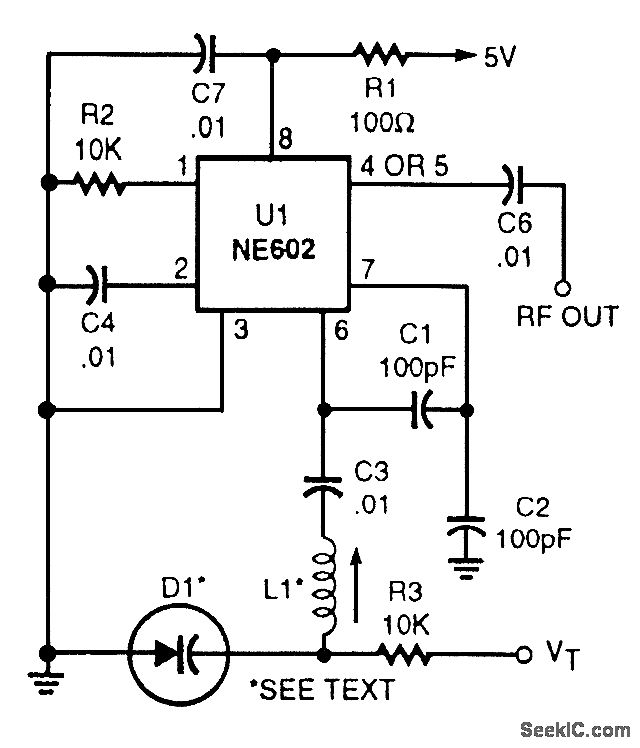
This voltage-tuned Clapp oscillator utilizes a varactor diode to determine its operating frequency. The diode used is an NTE614, and the inductor L1 has a value of approximately 7 microhenries. With this configuration, the oscillator can operate within a...
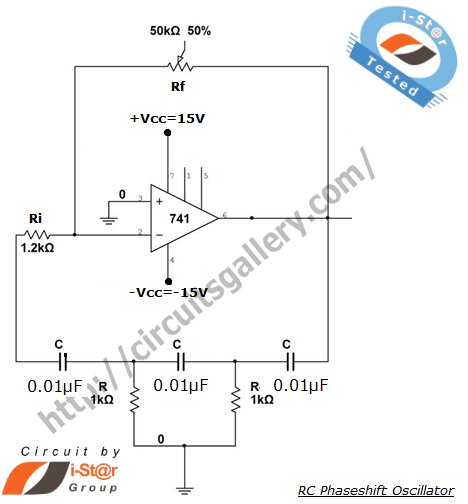
A phase-shifted oscillator can be constructed using a basic operational amplifier (op-amp), three resistors, and three capacitors. One of the resistors should be adjustable, while the other components should have the same value. This oscillator design exhibits low distortion...
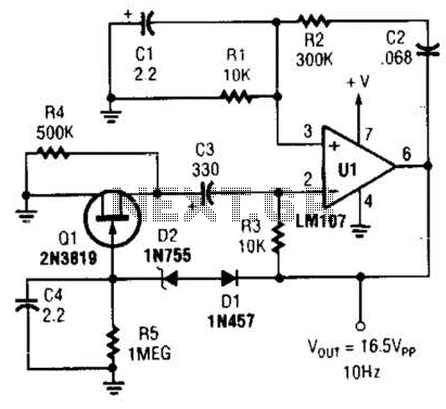
This Wien-bridge sine-wave oscillator utilizes a 2N3819 as an amplitude stabilizer. The 2N3819 functions as a variable-resistance element within the Wien bridge. The Wien-bridge oscillator is a type of electronic oscillator that generates sine waves. It employs a bridge circuit...
Warning: include(partials/cookie-banner.php): Failed to open stream: Permission denied in /var/www/html/nextgr/view-circuit.php on line 713
Warning: include(): Failed opening 'partials/cookie-banner.php' for inclusion (include_path='.:/usr/share/php') in /var/www/html/nextgr/view-circuit.php on line 713