
Metal Detector DIY

The CS209A metal detector circuit operates on the principle of inductance variation in response to nearby metallic objects. The oscillator within the CS209A generates an alternating current that flows through the 100 µH coil, forming an LC circuit. This circuit is sensitive to changes in inductance caused by the presence of metal, which alters the oscillation frequency.
When metal is detected, the change in inductance triggers the LED and buzzer. The LED serves as a visual indicator, while the buzzer provides an audible alert, enhancing the user experience. The variable resistor, VR1, plays a critical role in calibrating the circuit. Initially, VR1 is adjusted to a position where the circuit is inactive (away from any metal). As the user brings the coil closer to metal objects, the inductance change causes the LED to illuminate and the buzzer to sound, indicating detection.
Fine-tuning VR1 allows for sensitivity adjustments, ensuring that the circuit remains responsive to metal detection without false positives from environmental noise or other non-metallic influences. This feature is particularly important in practical applications, where the ability to discern between different types of interference can significantly enhance the effectiveness of the metal detector.
Overall, the design of this DIY metal detector circuit is efficient and user-friendly, making it suitable for hobbyists and professionals alike. The simplicity of the circuit allows for easy assembly and operation, while the functionality provided by the CS209A ensures reliable performance in detecting metallic objects.The heart of this DIY metal detector circuit is CS209A. The metal detector is build with one 100 µH coil. CS209A has one oscillator which forms a LC circuit, the inductance of the coil will change when it is near metal objects. LED 1 will light and the buzzer turns on when the coil is changing inductance. The setup is easy, VR1 is adjusted (away f rom any metal objects) so that LED 1 will light and the buzzer sounds on, and then VR1 will be trimmed until led and buzzer are off. 🔗 External reference
Related Circuits
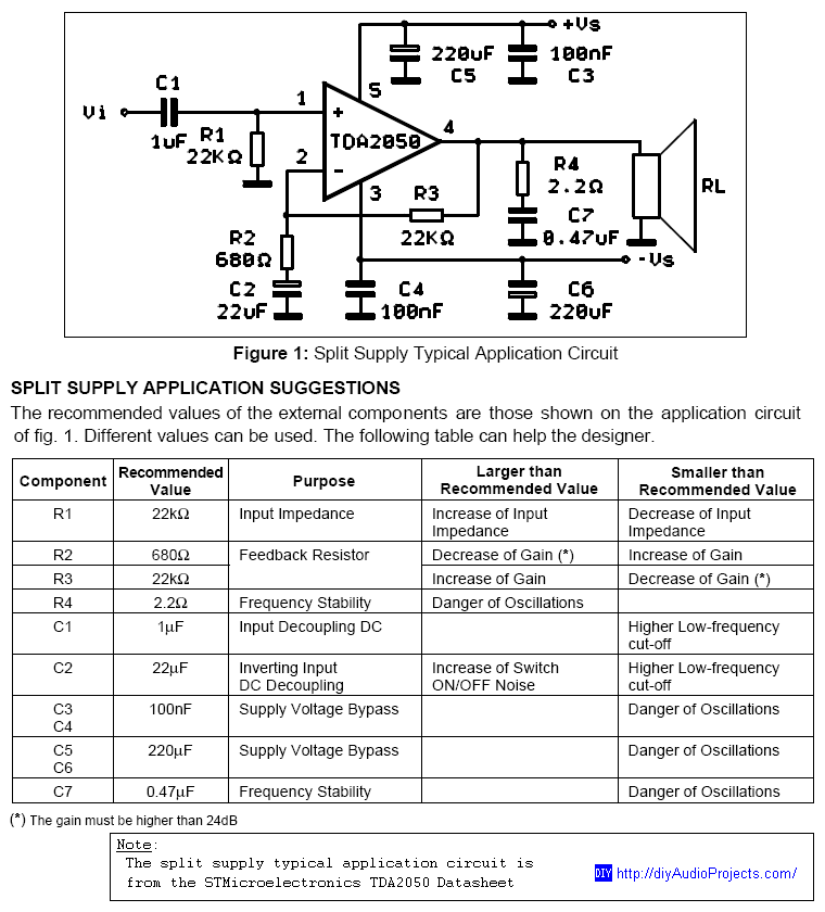
DIY TDA2050 Non-Inverting Chip Amplifier project constructed on a protoboard. The TDA2050 is a popular audio power amplifier integrated circuit designed for various audio applications. This non-inverting amplifier configuration is particularly valued for its simplicity and effectiveness in delivering high-quality...
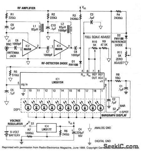
This RF detector can locate low-power transmitters (bugs) that are hidden from sight. It can sense the presence of a 1-mW transmitter at a distance of 20 feet, which is sensitive enough to detect the smallest bug. As the...
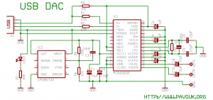
There is a significant interest in audio DAC design, particularly in creating a low-cost yet powerful audio DAC. This guide will provide instructions on how to build a personal audio DAC using the PCM2902 circuit. The project involves designing...
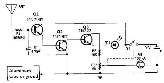
This ion detector circuit is designed to sense static charges and free ions present in the air. It is capable of detecting the presence of free ions, static electricity, or high voltage leakage. The project utilizes a short whip...

This circuit can be constructed using readily available, low-cost components, some of which may even be found in a junk box. The specified value of 22 for resistor R1 results in an average current of approximately 65 mA flowing...
One of the simplest methods of metal detection is through a beat frequency oscillator. The circuit consists of two balanced oscillators: one provides a reference signal, while the other acts as the detector element. The frequency of the reference...