
T-121 temperature sensors form a temperature control circuit diagram

The T-121 temperature control circuit utilizes a 555 timer IC configured in a Schmitt trigger mode to provide stable and reliable temperature regulation. The circuit operates by adjusting the variable resistors RP1 and RP2, which set the threshold levels for temperature detection. As the temperature sensor detects changes in ambient temperature, it outputs a corresponding voltage signal to the 555 timer.
The Schmitt inverter configuration is advantageous due to its hysteresis property, which prevents rapid switching of the relay in response to minor fluctuations in temperature. This results in a more stable operation and reduces wear on the relay contacts. The relay serves as a switching device that can control larger loads, such as heating elements or cooling fans, based on the output from the 555 timer.
The temperature sensor, typically a thermistor or a thermocouple, is positioned in the environment where temperature monitoring is required. Its resistance changes with temperature, providing a varying voltage signal to the input of the 555 timer. The circuit can be fine-tuned by adjusting RP1 and RP2, allowing for precise control over the activation and deactivation points of the relay.
Overall, the T-121 temperature control circuit is an effective solution for maintaining desired temperature levels in various applications, ensuring that the connected devices operate within safe temperature ranges. The inclusion of the Schmitt trigger and relay enhances the reliability and efficiency of the temperature control system.Adjust RP1, RP2 can be preset temperature control point, 555 circuit Schmitt inverter circuit with relay device automatically. T-121 temperature control circuit constituting th e temperature sensor as shown below:
Related Circuits
Short circuits or broken PCB tracks can be easily identified using a multimeter. However, this tool may yield inaccurate results when assessing the efficiency of a transistor or diode unless the device is unsoldered and removed from the PCB....
This circuit features a portable solid-state bright light utilizing the LT1932 integrated circuit. It can be powered by two AA dry or rechargeable pen-light batteries. The design allows for customization of the housing, enabling various applications such as a...

The design goals of this circuit were efficiency, simplicity, reliability and the use of field replaceable parts. A medium power solar system can be built with the SCC3, a 12V (nominal) solar panel that is rated from 100 milliamps...

A water Happy Valley-type four flashing lights string controller, electric bollard is designed for use with a type J Ding Japanese lantern. The circuit employs a specific integrated circuit (IC) utilizing CMOS technology. It features a black soft cream...
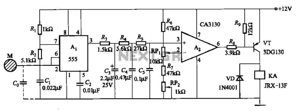
The circuit utilizes a 555 IC in conjunction with capacitors C1, C2, and a metal plate (tablet) M to create a distributed capacitance Co and resistor R1 connected to ground. Resistor R2 forms a self-excited multivibrator, while resistors R3...

Many enthusiasts utilize their PCs as data loggers, controllers, or web servers. In such instances, it is crucial to ensure that the machine remains powered for as much time as possible, even during a power outage or if the...